Hi all,
I have been mulling over an idea for a simple little PP 6080 amp recently. My experience with this valve is that it has less than unity gain (despite the mu of 2). I was thinking how I might really drive the output impedance down without introducing gNFB. I originally thought of doing some cathode feedback (with the ratios involved it would be a simple matter to hand wind bifilar coils on the toroidal outputs).
However this got me musing about the possibility of putting the whole transformer into the cathodes and be done with it. This would perform very similarly to anode loading and also introduce the cathode feedback I wanted. The practical implementation would be to have CCS delivering 100mA in each of the PP pairs cathodes, and then tying the points above them together with the output transformer, which would be left floating between the cathodes. I would anticipate something like a 10ohm to 1000Kohm transformer.
Sounds like a neat idea - but what am I missing.
Shoog
The TCJ Push Pull calculator software has this basic design and this tube in it, so for $29 you can sim to your heart's desire.
http://www.glass-ware.com/programs/TCJ_Programs_files/page0019.htm
http://www.glass-ware.com/programs/TCJ_Programs_files/page0019.htm
Hi Shoog !
Wherever is the load -in plates or in cathodes- it must remain the same if you expect to obtain the same output power.
Your driver must deliver the usual "twice the bias" pk to pk level at each grid, plus the pk to pk level appearing between the cathodes, in short "very huge" but at almost no load, no Miller effect etc...
Consider using a bootstrap scheme")
My 2 pence.
Yves.
Wherever is the load -in plates or in cathodes- it must remain the same if you expect to obtain the same output power.
Your driver must deliver the usual "twice the bias" pk to pk level at each grid, plus the pk to pk level appearing between the cathodes, in short "very huge" but at almost no load, no Miller effect etc...
Consider using a bootstrap scheme
My 2 pence.
Yves.
I know that the driver would be a bit problematic but there is a way of avoiding the need for an additional power transformer, which I have successfully used in the past.
Generate a negative rail from the main transformer and hang the driver stage off an input transformer. This kills two birds with one stone as it allows you to run a LTP with the whole gain of the triodes preserved, and secondly it gives you twice the voltage for the driver to play with.
Shoog
Generate a negative rail from the main transformer and hang the driver stage off an input transformer. This kills two birds with one stone as it allows you to run a LTP with the whole gain of the triodes preserved, and secondly it gives you twice the voltage for the driver to play with.
Shoog
A few days back I ran accross a schematic of an Electro Voice amp: Model A100.
This amp has the OPT in the cathode...
It can give you some ideas...
More here...
http://circlotron.tripod.com/
Worth a look.
Tarzan
This amp has the OPT in the cathode...
It can give you some ideas...
More here...
http://circlotron.tripod.com/
Worth a look.
Tarzan
Your driver must deliver the usual "twice the bias" pk to pk level at each grid, plus the pk to pk level appearing between the cathodes, in short "very huge" but at almost no load, no Miller effect etc...
Since I will be running the 6080's at 100V and 100mA, which equates to about 30V bias, the actual driver voltage required is about 120V Peak to Peak, which should be doable with the anticipated 260V available from the two rails. This only leaves one further problem - how to get 120V from 2V input in a two stage design.
Shoog
I was just thinking about my proposal and came up with a slight problem. My original idea was to get the transformer to take over differential communication duties in the output stage. However even though the current seen at either end of the transformer would be the same and hence effectively zero, since the 6080's are likely to be mismatched the DC bias point for each side will be different so the DC voltage on either side will be sightly different. Since the resistance of the transformer is so low, even a slight voltage mis-match will produce a considerable current across the transformer - leading to saturation.
So I was thinking if I ground the center tap of the primaries and then place the CCS in the actual cathode leg of the 6080, between the triode and the transformer, this will ensure balanced current across the transformer, and the CCS will take up the voltage difference between the two legs. Unfortunately the tightly differential nature of the output stage is lost.
Edit:
Having just thought about the last proposal, there is a chance that the CCS will spring up and down to the signal leaving their cathodes at a stable zero volts, ie no output. So a third proposal is in order. Split the primary into two halves, place a CCS between earth and one side of the primary, and the same for the other side. Current is forced to balance and the CCS will take up any voltage difference.
Shoog
I have been experimenting with cathode follower based output stages for about two years now. They show considerable promise despite the drawbacks. The obvious drawback is the BIG drive voltage that is required. Assuming a "perfect" cathode follower (gain = 1) the drive voltage is equal to the voltage required across the output transformer. So the solution is to use a low impedance OPT and output tubes that can deliver big current. The 6AS7 is a start. I have switched to the 6336A or some big sweep tubes due to their high cathode current capability.
Cathode followers like all circuits are not perfect. The drive voltage requirements are higher than the output requirements. There is some distortion since the bias voltage on the tube varies with the cathode to plate voltage which varies with the signal, hence the drive voltage requirements are slightly non linear. What if we could keep the cathode to plate voltage constant across the tube?
Back in 1957 a brilliant engineer named MacDonald devised a circuit to solve both of these issues. I got so interested that I built a SE amplifier based on the augmented cathode follower circuit. It worked well. See this thread:
http://www.diyaudio.com/forums/showthread.php?s=&threadid=114021&highlight=
More cathode follower experiments are here:
http://www.diyaudio.com/forums/showthread.php?s=&threadid=105859&highlight=
These were all SE circuits but I have experimented with some push pull designs using some of the cheap sweep tubes that I got last summer on sale. Yes you can put a CCS in the cathode of each output tube, and tie the OPT between the two cathodes. I did this and it does work. You need to make the grid bias adjustable on one of the tubes to take out the offset. You can put an oil cap in series with the OPT if needed to solve the DC issue.
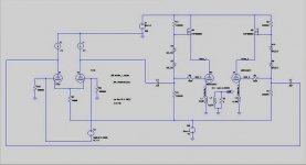
I have included a simulation of a push pull cathode follower. It uses a mosfet to keep the cathode to plate voltage constant. The simulator shows that 75 watts can be achieved in class A. The tube current is 300 mA which requires a 6336A or a big sweep tube. 600 V P-P of drive is required to reach 75 watts. I had a very similar circuit running on the bench last year. These experiments were all limited by my power supply and the available drive voltage. I now have a 1KW power supply and am working on a better driver board. More cathode follower experiments will follow.
Cathode followers like all circuits are not perfect. The drive voltage requirements are higher than the output requirements. There is some distortion since the bias voltage on the tube varies with the cathode to plate voltage which varies with the signal, hence the drive voltage requirements are slightly non linear. What if we could keep the cathode to plate voltage constant across the tube?
Back in 1957 a brilliant engineer named MacDonald devised a circuit to solve both of these issues. I got so interested that I built a SE amplifier based on the augmented cathode follower circuit. It worked well. See this thread:
http://www.diyaudio.com/forums/showthread.php?s=&threadid=114021&highlight=
More cathode follower experiments are here:
http://www.diyaudio.com/forums/showthread.php?s=&threadid=105859&highlight=
These were all SE circuits but I have experimented with some push pull designs using some of the cheap sweep tubes that I got last summer on sale. Yes you can put a CCS in the cathode of each output tube, and tie the OPT between the two cathodes. I did this and it does work. You need to make the grid bias adjustable on one of the tubes to take out the offset. You can put an oil cap in series with the OPT if needed to solve the DC issue.
I have included a simulation of a push pull cathode follower. It uses a mosfet to keep the cathode to plate voltage constant. The simulator shows that 75 watts can be achieved in class A. The tube current is 300 mA which requires a 6336A or a big sweep tube. 600 V P-P of drive is required to reach 75 watts. I had a very similar circuit running on the bench last year. These experiments were all limited by my power supply and the available drive voltage. I now have a 1KW power supply and am working on a better driver board. More cathode follower experiments will follow.
Attachments
Thanks for that Tubelabs,
My needs are much more modest - a measly 7Watts will make me happy.
Looking at your circuit, how much voltage does the mosfet consume in doing its job.
I am currently running my preamp as a SLCF ala Allan Wrights FVP5. I am very happy with it and know the principles quite well. I have an improved version in the pipeline - but other things are drawing me away from finishing it.
Shoog
The mosfet is used to dynamically adjust the plate voltage in step with the audio. The zener diodes on the gate of the fet set the plate to cathode voltage across the output tube. The voltage is chosen based on the characteristics of the output tube. I set the voltage to a point where the output tube can pass the needed peak current with good linearity. This is fairly low with the right tube. A 6LW6 can crank out 1 AMP of current with 100 volts across it. The 6336A and the 6AS7 can run at 100 volts at lower current. Keeping the voltage constant across the output tube greatly lowers the distortion. Keeping the voltage low reduces the dissipation, although it just moves it to the mosfet. In this design most of the voltage is dropped across the mosfet (about 300 volts) which results in the need for a big heat sink. A smaller amp would have more reasonable dissipation requirements. You don't need to use a mosfet either, the upper element in my augmented cathode follower amp was the other half of the 6336A tube. The schematic was somewhere in the included links.
The mosfet can be replaced by a digitally controlled SMPS to eliminate the dissipation in the upper element. I built one of those too.
The mosfet can be replaced by a digitally controlled SMPS to eliminate the dissipation in the upper element. I built one of those too.
Its all a question of how you look at things. The triode is still doing its triode thing (as much as a cathode follower is doing a triode thing) just in a more linear manor. I suppose the proof would be, if you substituted a diode would it behave the same ? Anyone care to simulate.
Tubelabs - what do you feel would be the minimum the Mosfet would need to be happy. Would it be the 120V of anticipated drive (plus a bit), or could it pull it off with just a few tens of volts. The whole design is inefficient enough as is, without loading things down with more inefficiency.
Shoog
Tubelabs - what do you feel would be the minimum the Mosfet would need to be happy. Would it be the 120V of anticipated drive (plus a bit), or could it pull it off with just a few tens of volts. The whole design is inefficient enough as is, without loading things down with more inefficiency.
Shoog
Shoog said:Its all a question of how you look at things. The triode is still doing its triode thing (as much as a cathode follower is doing a triode thing) just in a more linear manor. I suppose the proof would be, if you substituted a diode would it behave the same ? Anyone care to simulate.
A triode is a controlled by a grid voltage diode.
It is useful to remember when thinking of curves and distortions. Particularly, neither emitter follower nor cathode follower is a magical device with zero distortions and zero output resistance; it is a linearized by feedback diode (either solid state diode, or a vacuum one).
Had you considered a cathode-follower driver, direct-coupled to the output tubes?
Your bias would then be set up in the grid circuit of the driver tube, and your voltage amplifier would have an easier time with the input grid capacitance.
The amp should be good for about 10 watts total, depending on the plate voltage.
You're going to need more than a simple gain stage to make the voltage swing. Either you will need a very high power supply voltage, two stages of gain, or a high-gain voltage amp, either pentode or cascode.
I favor the cascode, if set up right they can be really good performers.
Your bias would then be set up in the grid circuit of the driver tube, and your voltage amplifier would have an easier time with the input grid capacitance.
I don't really want to go direct coupled, and I don't think the grids of the 6080 will be that difficult a load.
You're going to need more than a simple gain stage to make the voltage swing. Either you will need a very high power supply voltage, two stages of gain, or a high-gain voltage amp, either pentode or cascode.
Yes i was scratching my head on that one. A CCS loaded LTP using ECC81 might just hack it - but isn't really very appealing. I have had success with using a 6AU6 LTP in my current Tabor clone - with a gain of about 60x it should do the trick with a 2v input. This can be achieved with a plate current of about 5mA and leaves plenty of input headroom. Of course the secret is to drive both the inputs - which requires an input transformer or balanced drive. Simple transistor screen regulation should keep things singing.
Shoog
The issue that you have if you don't use a direct-coupled driver is that the grids of the 6080 will need some fairly low values in order for the bias divider network to maintain control. This will be in direct conflict with the size of the coupling caps- the bigger you make them, the less transparent the amp.
Using the direct-coupled approach has no downside against that, however to do it right you will need a bi-polar power supply. That would not be hard to set up though, and would also give you good options should you want to do a CCS and LTP voltage amplifier. The advantage is the amp will have instantaneous overload recovery and you can keep the coupling caps a lot smaller. That makes them cheaper and more transparent at the same time.
I've found that a good 2-stage CCS (all-tube) is the key to getting good performance in the LTP.
Shoog said:
Yes i was scratching my head on that one. A CCS loaded LTP using ECC81 might just hack it - but isn't really very appealing. I have had success with using a 6AU6 LTP in my current Tabor clone - with a gain of about 60x it should do the trick with a 2v input. This can be achieved with a plate current of about 5mA and leaves plenty of input headroom. Of course the secret is to drive both the inputs - which requires an input transformer or balanced drive. Simple transistor screen regulation should keep things singing.
Shoog
hey Shoog,
I have a pair of amps running LTP pentodes, and a pair running a triode/MOSFET cascode( MOSFET on 'top'). I have some issues with the screen current; the cascode does not have this 'feature'. Finding a pentode with reasonable g2/plate current seems to be the trick here. I am using the 6AC7 instead of the 6AU6. Both implementations have the same sort of horizontal plate curves( and spacing )...and the g2 current seems to work out OK...
cheers,
Douglas
hey Shoog, I have a pair of amps running LTP pentodes, and a pair running a triode/MOSFET cascode( MOSFET on 'top'). I have some issues with the screen current; the cascode does not have this 'feature'. Finding a pentode with reasonable g2/plate current seems to be the trick here. I am using the 6AC7 instead of the 6AU6. Both implementations have the same sort of horizontal plate curves( and spacing )...and the g2 current seems to work out OK... cheers, Douglas
The 6AU6 and the 6AC7 look very similar, though the 6AU6 looks to have slightly more even line spacing. Essentially they look almost like drop ins for each other.
In my current amp I have the screens referenced to a VR150 which works well, but introduces a bit of cross talk between channels. If I could be bothered I would add a small transistor buffer or an extra VR150 for the other channel.
I was think of using a simple transistor referenced to a trimable resistive voltage divider to set the screens on this one. If I pass enough standing current through the resistor chain it should present a nearly constant voltage. How are you dealing with your screens??
Shoog
- Status
- This old topic is closed. If you want to reopen this topic, contact a moderator using the "Report Post" button.
- Home
- Amplifiers
- Tubes / Valves
- Transformer in the cathodes ??