Noisey gain boost
Hi again ! Thanks to everyone who has responded to my previous threads...I have gained some good insights.
Anyway...I have a VOM amp from an old reel to reel. Single ended with a 6V6 output, 12AX7 preamp, and 6X4 rectifier. Very common and basic...both power and preamp are cathode biased, but the 12AX7 was not bypassed, so I took this as an opportunity to add a cap with a switch for a gain boost. The boost is reaaly cool, but there is a lot of noise. The first half of the 12AX7 has a 1K cathode resistor, the second half a 1.5K. I only bypassed the first half with a 22@25 'lytic. I've tried moving the switch and the ground as well as trying a different cap...thinking I had a bad one. No difference. Would it help to replace the switch with a jack and control the boost remotely ? Should I switch the bypass cap to the second half of the 12AX7? Any suggestions would be appreciated...thanks !
what I mean is if it works fine with just the cap you can then control the boost down before the amp.
in the old days they would not use this type of boost as you have found as so as you put a switch in,........ it all goes tits up.
so they would go for anode boost effect etc.
but now with the better graphic equalizers in most homes.........its easy
in the old days they would not use this type of boost as you have found as so as you put a switch in,........ it all goes tits up.
so they would go for anode boost effect etc.
but now with the better graphic equalizers in most homes.........its easy
More gain...good, noise...bad
Hi Pointy...thanks for the reply. No I did not try it without the switch...I need to clarify the application here. I am mainly a guitar amp junkie who really dislikes modern tube amps. I will try removing the switch, but it defeats the purpose of the boost. That's why I thought using a remote switch might help....
Hi Pointy...thanks for the reply. No I did not try it without the switch...I need to clarify the application here. I am mainly a guitar amp junkie who really dislikes modern tube amps. I will try removing the switch, but it defeats the purpose of the boost. That's why I thought using a remote switch might help....
It might help to know how the unit is wired at the input and the grounding scheme used. For example is shielded cable used from input jack to grid of first tube? Is star ground, buss ground or "wherever it fits" ground used? Is the noise high freq., broadband white noise, or hum?
What I am thinking is that the amp was designed with a certain level of gain in mind. With higher gain more extensive measures may be required to keep the noise in check.
What I am thinking is that the amp was designed with a certain level of gain in mind. With higher gain more extensive measures may be required to keep the noise in check.
it may be worth your while waiting for someone else to post on this subject.
but as far as i recall the way to use the cathode bias bypass as a bass boost would be to fit the cap in place and then use pre-amp controls to tame it down.
it was thought that it messed up the valve capacitance but it was found to be something more like the switch started acting in part like a capacitor.
up to the 1970s designers would not use it and as far as i know no real
way has been found around it.
i would have normally thought if it was that the switch acting as a capacitor that you could just put a small resistor in between but from what i have heard it does not work out like that.
so i think its best to wait for someone with more current information.
Ok...I took out the switch and the hum dropped considerably. But this is not a good thing as I wanted to have a switchable gain boost. The input to the grid is shielded 2 conductor wire, the ground is at the same spot as the cathode resistor...a terminal lug, and the noise is hum that increases with volume. 

Can you give us pics of the underside? I would start looking at the heater wiring (is it tightly twisted, routed around the edge of the chassis, kept away from the inputs etc.). Are the PS filtering caps grounded at the same point as the signals or a separate location close to the power transformer? Also look at the power supply filtering. Your circuit may need better filtering. It is also possible that the routing of the wiring to your switch is less than optimum. Keep the wires short and away from heater and PS wiring. If you have to cross other wires do so at a 90 degree angle.
Another thing to look at is the heater winding reference. If the heater winding is grounded the hum might be improved by elevating the heater somewhat. Easiest way is to connect the heater winding center tap to the cathode of the output tube instead of the chassis ground.
Another thing to look at is the heater winding reference. If the heater winding is grounded the hum might be improved by elevating the heater somewhat. Easiest way is to connect the heater winding center tap to the cathode of the output tube instead of the chassis ground.
you can do the same thing so you have the boost but you would need to do it at the anode.
what happens is the contacts of the switch gets a small cover of dirt grease or dust and then acts as a intermittent capacitor.
if you change to the anode the increase of volts will over come this effect.
now days you may be able to use a mosfet or transistor as a switch
but i have no knowledge of anything working at Kr bypass.
sorry as I said at the start (it may be worth your while waiting for someone else to post on this subject)
but what you will need to do is give the same resistance which ever way the anode by pass is switched
and I am going to have to admit that the way to do it I have not got at hand at the moment
what you will need to do is balance the resistance the same as with just the anode resistor
and then when switched may by using a double pole switch
so you can change from the single resistor to a balanced resistors with the by pass (same resistance)on the throw.
but as I have said it will be best to see what the others say about this
this is all i remember of bass boost on a se reel to reel
(without changing the original sound of the amp)
you would replace the anode resistor with the circuit in the picture
(which i hope has come out OK)
then when you place the anode resistor in the red area
you must have the same resistance across everything in the blue area
i believe the lower of the two resistors in the blue area should have the greatest resistance of the two resistors in the blue area
remember to use components that are of the right working volts, watts, etc.....
the switch should be a fast snap over type
this will give a tone boost
BUT BEFORE YOU TRY THIS WAIT FOR SOMEONE WHO IS IN THE KNOW TO HAVE THEIR SAY...........!
Attachments
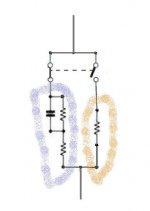
i would try to keep it so the non bypassed resistor in the blue area is at 90% of the total resistance within the blue area.
this is the only boost that i know of that works on a se small amp so that when you throw the switch back you will have the true sound of the original amp.
this is the only boost that i know of that works on a se small amp so that when you throw the switch back you will have the true sound of the original amp.
Here's the radiotron designer's handbook on tone controls, more ways to cut/boost in there than you can shake a guitar at:
http://headfonz.rutgers.edu/RDH4/CHAPTR15.PDF
http://headfonz.rutgers.edu/RDH4/CHAPTR15.PDF
if you mean... as in the drawing with the resistor in the red area being the original plate resistor and every thing in the blue area being the same resistance as the plate resistor.
and you will want the resistor at the bottom of the blue area the non by-passed one to be about 90% of the total resistance in the blue area, no less
then you can try out a few non polarized capacitors as long as all the parts are of the working volts needed.
but I would still want to see someone else give this design the thumbs up before trying it out,
as i have not done any work on valve amps in the last 30 years
( i am a bit rusty) ..
- Status
- This old topic is closed. If you want to reopen this topic, contact a moderator using the "Report Post" button.
- Home
- Amplifiers
- Tubes / Valves
- Noisy gain boost