Hi everybody,
I'd like to throw the circuit below out in the open and get some comments on it.
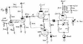
I'm not at all experienced in designing my own circuits. The tube choices are based mainly on what I have lying around, it's the overall topology I'm not so sure about. Will it work well?
Credit where it's due: the voltage stage (around the 6SN7) was taken from the 'Lyrebird' amp.
Please comment,
nukkel
I'd like to throw the circuit below out in the open and get some comments on it.
I'm not at all experienced in designing my own circuits. The tube choices are based mainly on what I have lying around, it's the overall topology I'm not so sure about. Will it work well?
Credit where it's due: the voltage stage (around the 6SN7) was taken from the 'Lyrebird' amp.
Please comment,
nukkel
Attachments
I have never worked with the GM70, so I'll let others comment on the circuit and specific op-points.
However, the EL84 is running at 93% of max power dissipation. I recommend you replace it with another power pentode with larger plate dissipation - i.e. another 807 or an EL34.
Enjoy,
However, the EL84 is running at 93% of max power dissipation. I recommend you replace it with another power pentode with larger plate dissipation - i.e. another 807 or an EL34.
Enjoy,
Kavamel,
Running the output tube as a grounded grid and no NFB will give you a VERY high output impedance - if that's what you want then go for it.
But if it's not what you or your speakers want, then you will have every odd sounding amp.
Your driver staes could be much simplier if you use conventional grid drive, and the OPZ will be down into a "normal" range.
Regards, Allen (Vacuum State)
Allen Wright said:Kavamel,
Running the output tube as a grounded grid and no NFB will give you a VERY high output impedance
Regards, Allen (Vacuum State)
How do you figure that Allen? The cathode impedance does change the plate characteristic. Roughly by factor of mu times the output Z of the driving stage.
The bigger issue I see here is cap coupling. The cathode impedance( load to be driven ) is ~200 Ohms. The 211 is much more responsive to this sort of thing; its A1 grid drive capability is small compared to what is possible with grid current. Driving the cathode leaves no step change in load when grid current starts to flow, as well as using the grid as a screen to avoid Miller. Zero bias with B+ of ~600V can yeild nearly 100W in PP without resorting to AB. Since we're taking SE, the drive is slightly more difficult...still need a power amp in front of it.
cheers,
Douglas
The bigger issue here is the driver has to deliver the same current the output transformer will see, and a voltage swing roughly twice of an idle grid-cathode bias. Think of such power requirements, and add 100 Ohm load (2 x 200 Ohm in parallel) and guess, do you need an output stage if your EL84 delivers more power than you get on the speaker...
I played with cathode drive several years ago when I was designing my 845SE. I never could get it to sound right, so I kept experimenting and wound up with what I now call PowerDrive.
There are several ways to do cathode drive that are far simpler than this. Some of these ideas work with the 845 because of its large bias and drive requirements, they may be harder to implement with less voltage.
1) Use a 6AS7 for your output tubes cathode resistor and drive its grid. The grid voltage on the 6AS7 sets the current through the output tube stack, and you get extra gain (not much).
2) Make an LTP using the output tube for one half and a decent sized triode (or triode wired pentode) of similar Mu for the other half (I used a KT88). Hang a CCS chip in the tail. The drive goes to the smaller tubes grid and its plate goes to a medium voltage supply.
3) Use a P channel mosfet in the cathode, Source to the cathode , drain is grounded, bias pot and drive to the gate. This works the best.
I never really thought about the output impedance, but I believe Allen is right. The cathode to grid drive voltage is the same whether the grid is grounded and the cathode is driven, or the cathode is grounded and the grid driven. The cathode to plate voltage is not the same. There is a positive feedback type action going on since the plate to cathode voltage is modulated by the drive voltage. This will raise the output impedance but may allow for more power output from a given tube. I was trying to exploit the "more power" idea, but it sounded poor.
Ham radio guys realized long ago that the drive power is added to the output power allowing for a bit more power output from a given amount of DC power input to the final stage. This is why grounded grid RF amplifiers were popular when the FCC rules specified a maximum DC input to the final stage. Those rules were changed a long time ago (I don't remember exactly when).
I never really thought about the output impedance, but I believe Allen is right.
I think he is too. The driver and output stage together are working kind of like an AC coupled cascode variant. Good for a pre-amp, but probably the worst candidate for an audio amplifiers output stage.
The bigger issue I see here is cap coupling.
That would defiantly be another major obstacle.
I wouldn't pursue that output stage, if I were you. Sure you will probably get sound out of it, but I can't imagine the results being better than a conventional grid driven config.
Thanks everyone for your feedback. Based on it I guess the circuit as it is isn't worth building. At the moment I see two best options:
A- Stick with conventional grid drive and keep the output tube in A1 as much as possible (to avoid the sudden load change to the driver)
B- Try a better way of implementing cathode drive (Tubelab, thanks for your suggestions! I'll be looking into them)
I'm leaning towards (A), but I'm also curious how those on-paper benefits of a grounded grid stage would translate into sound...
All the best
kavermei
Allen Wright said:I'm curious. What "on paper"benefits do you expect from ground grid operation?
I'm not aware of any...
Regards, Allen (Vacuum State)
Maybe that the driver requirements are about the same in class A1 and A2 and that the transition from A1->A2 not will affect the driver very much?
Jan E Veiset
Allen,
basically what Jan and Douglas are saying, most importantly the driver sees a constant load regardless of grid current.
Also (if I remember this correctly, anybody pls correct me otherwise...) grounded grid gives a slightly higher amplification factor compared to common cathode (1+mu vs. mu)
Finally the drive signal is in series with the load (OPT primary) so, other than the fact that the driver contributes directly to the output power, I'd guess this would have an effect on the sound too.
kavermei
This is my last test about GM70 performances
http://www.audiodesignguide.com/Claudio845/test_GM70.html
http://www.audiodesignguide.com/Claudio845/test_GM70.html
- Status
- This old topic is closed. If you want to reopen this topic, contact a moderator using the "Report Post" button.
- Home
- Amplifiers
- Tubes / Valves
- GM-70 cathode feed SE amplifier