Hello,
My brother in law has a pair of McIntosh MI-75 monoblock amps and he asked me for help. One of them is blowing fuses and his technician said the output transformer is shorted. OK, I called Audio Classics in NYC and another McIntosh authorized service center and they told me they charge $600 to rebuilt the damaged transformer.
  They also said this part is no longer available. Any other options? Do you know anyone outside the Mcintosh network that perform this kind of service? I guess McIntosh Service Centers or dealers charge a flat fee of $600 for this kind of service. Any advice will be appreciated. Thanks.
My brother in law has a pair of McIntosh MI-75 monoblock amps and he asked me for help. One of them is blowing fuses and his technician said the output transformer is shorted.
OK, I called Audio Classics in NYC and another McIntosh authorized service center and they told me they charge $600 to rebuilt the damaged transformer. They also said this part is no longer available. Any other options? Do you know anyone outside the Mcintosh network that perform this kind of service? I guess McIntosh Service Centers or dealers charge a flat fee of $600 for this kind of service. Any advice will be appreciated. Thanks.hey-Hey!!!,
See Heyboer TX in Grand Haven MI. They've got great skill at rewinding vintage output TX's. They've done some very complex Peerless designs for me( reverse engineering to make copies of a single sample ). With a rebuild like you propose, you'll probably use the original cores( C's IIRC), and re-pot them in its original can. Very reasonable prices too.
With the McIntosh multi-filar primaries, wire insulation is important; maximum thickness is required.
Cheers,
Douglas
")
I had Mercury Magnetics rewind a MI-200 OPT a few years ago, they charged $750 for that job. The MI-200 OPT has 3 separate C-cores on one bobbin and runs at approx. 1000VDC. They had to order special mag wire and such for the high voltage. I would think the MI-75 would be less of a job.
Craig
Craig
llwhtt said:I had Mercury Magnetics rewind a MI-200 OPT a few years ago, they charged $750 for that job. The MI-200 OPT has 3 separate C-cores on one bobbin and runs at approx. 1000VDC. They had to order special mag wire and such for the high voltage. I would think the MI-75 would be less of a job.
Craig
hey Craig,
Your core description makes me curious. I can see a single pair of C's arranged to approximate a torroid, or two pairs like an E-I...but three pairs makes no sense at all to me. Care to elaborate?
cheers,
Douglas
I had bought a McIntosh MI 350 and found it had a
blown output transformer.
I had brought it over to Bob Hovland to check it out.
He recommended me to go to a guy in Wisconsin.
I can't remember who it was...You might try a google search.
It cost me 1000.00 to have it redone.
Steve @ Apex Jr
blown output transformer.
I had brought it over to Bob Hovland to check it out.
He recommended me to go to a guy in Wisconsin.
I can't remember who it was...You might try a google search.
It cost me 1000.00 to have it redone.
Steve @ Apex Jr
Douglas,
I'll try to explain it, if you were to look down on the square paper bobbin from above (windings horizontal) there would be a complete core on the left, on the right and one perpendicular to the first two, top or bottom. I saw it with my own eyes, even hooked it up to check it out before they potted it. The can(box) it goes into must be at least 7" on all sides. We think they just used cores they had on hand and used as many as it took to do the job and it took three. Definitely was NOT the most elegant way to do it but you have to remember this was an industrial amplifier not high end. Hope my explanation is clear enough, if not I'll to draw some diagrams.
Craig
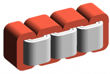
Here's a picture of a three-pase C-core transformer. If the last core and bobbin are removed, you get a triple C-core transformer with primary and secondary windings in separate bobbins.
Not what you described, but I cannot picture the third "perpendicular" core...
Not what you described, but I cannot picture the third "perpendicular" core...
Attachments
Bandersnatch said:
hey Craig,
Your core description makes me curious. I can see a single pair of C's arranged to approximate a torroid, or two pairs like an E-I...but three pairs makes no sense at all to me. Care to elaborate?
cheers,
Douglas
I think I got it...
The cores are arranged in the form of in inverted "T" with each segment being a core. ASCII art below:
_|_
The intersection point of all three cores goes thru the center of the bobbin.
cchean,
It seems from the above posts that this will be an expensive project. At least at my funds level 600.00 dollars will buy a lot of other items.
The good thing is you have a transformer to go by. If you can find someone who winds electric motors for a living in Charlotte at a large electric motor repair facility they should be able to replicate the windings. Mcintosh does not spend a great deal of time closely stacking the windings side by side like you might if you did it. They use very fast spinning bobbins -- usually orlder women doing the work -- and just add wire to a specific number of turns then strap the cores around them and pot.
Any decent winder who measures the wire gauge and counts the turns ratio willl be able to do this. Modern insulation is far superior to what was available in the '70's. Have them place the unit in the VPI tank when finished -- vacuum pressure impregnated-- which will yield a superior unit.
This is something you will most likely need the winder to do on his own time as a side job.
I had one of my-- mc2250 -- transformers done this way at Tampa armature works here in Macon. It turned out perfect. It easily withstands a 3500 volt short to turns test.
If you go this route PLEASE post the winding spec's here on the forum for the rest of us. Tad
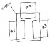
I drew a diagram, scanned it, and tried to attach it but it's too big. So I'll explain it again, think of Stonehenge, a core on each side and one across the top. Or the symbol for Pi, one on each side and one across the top. The sides of the bobbin are longer than the cores are wide, the top core fills the gap. Clear as mud now, right?
Craig
Craig
llwhtt said:I drew a diagram, scanned it, and tried to attach it but it's too big. So I'll explain it again, think of Stonehenge, a core on each side and one across the top. Or the symbol for Pi, one on each side and one across the top. The sides of the bobbin are longer than the cores are wide, the top core fills the gap. Clear as mud now, right?
Craig
Craig, could you pls email me a copy of your sketch?
jose_korneluk AT bellsouth.net
Thx,
http://www.manta.com/coms2/dnbcompany_ccqypkg
Dennis Hoyer, transformer rewinder in Milwaukee, WI.
Been around a long time. Seems to know his stuff. Probably expensive but who knows in this economy.
Dennis Hoyer, transformer rewinder in Milwaukee, WI.
Been around a long time. Seems to know his stuff. Probably expensive but who knows in this economy.
I have some connections to Milwaukee, so I was curious and googled Dennis Hoyer. Here is an ad where is lists Mac transformers as something he winds:
http://www.roger-russell.com/autran.htm
pj
www.wildburroaudio.com
http://www.roger-russell.com/autran.htm
pj
www.wildburroaudio.com
llwhtt said:I drew a diagram, scanned it, and tried to attach it but it's too big. So I'll explain it again, think of Stonehenge, a core on each side and one across the top. Or the symbol for Pi, one on each side and one across the top. The sides of the bobbin are longer than the cores are wide, the top core fills the gap. Clear as mud now, right?
Craig
Drawing from Craig...
Attachments
cchean said:
My brother in law has a pair of McIntosh MI-75 monoblock amps
Hi cchean ,
Does your brother in law have those monoblocks yet ???
Or he already sold them ??
What solution have you ( he ) adopted ??
Regards,
Carlos
- Status
- This old topic is closed. If you want to reopen this topic, contact a moderator using the "Report Post" button.
- Home
- Amplifiers
- Tubes / Valves
- Mcintosh amps transformer rewinding, help needed please!