Also intended for use with 1625 outputs as well since I have a few of them too. Comments and suggestions? Designed around available parts - please don't go suggesting esoteric unobtainiums.
Shoog, I know you've done this including the toroid OPT - expert opinion?
Shoog, I know you've done this including the toroid OPT - expert opinion?
Attachments
aardvarkash10,
The 6J5 is unsuited as a driver in this application: its mu is too low as is its internal resistance. The output stage is acting as a current to voltage converter. As John Broskie wrote in the March 2001 issue of Tubecad Journal ‘The key point is that the impedance looking into the converter must be high, so as to give the grid the freedom of movement required to convert the incoming current into voltage. Fortunately, designing high output impedance tube circuits is an easy task.’
Additionally, as the feedback is lowering the gain of the amp, the driver requires a fairly high mu.
Alex specified the 12AT7 for a good reason. Pentodes are also good in this role.
cool - 6j7 then
Again, 6j7 cos I have them on hand, or can get them cheap. Even uses a top-cap so thats three top-cap tubes in the package!
Looking to run the 807 at around 50ma, and according to the 807 datasheet I'm looking toward 11W output. I know the 807 is inclined to oscillations - should I include an anode stopper?
Should the zener string holding the screen voltage be bypassed with a cap?
Is the cap on the OPT enough to avoid DC saturation? Or too much???
The CCS is designed (more thrown together...) following Gary Pimm's design guide and in response to the difficulty finding a high-voltage shunt reg like the 10M45. Any known difficulties with Gary's design (apart from his comments refering ot the superseded nature of it)?
ahhhhh, so much to learn...
Re: cool - 6j7 then
I did. You can make one with N= 10 (#18AWG); ID= 7/16 in. Space wind that coil, and connect in parallel with a 2W, 100R C-comp resistor. (If you can't find any, four 470R / 0.5W C-comps in parallel also works just fine.) Fit the resistor(s) inside the coil, and connect right to the plate cap. I would also definitely recommend screen stoppers: 1K5. Otherwise, instabilities are likely to occur.
It could be 100pF and it would most definitely avoid DC saturation. So long as it doesn't short out, it'll stop the DC.
aardvarkash10 said:Looking to run the 807 at around 50ma, and according to the 807 datasheet I'm looking toward 11W output. I know the 807 is inclined to oscillations - should I include an anode stopper?
I did. You can make one with N= 10 (#18AWG); ID= 7/16 in. Space wind that coil, and connect in parallel with a 2W, 100R C-comp resistor. (If you can't find any, four 470R / 0.5W C-comps in parallel also works just fine.) Fit the resistor(s) inside the coil, and connect right to the plate cap. I would also definitely recommend screen stoppers: 1K5. Otherwise, instabilities are likely to occur.
Is the cap on the OPT enough to avoid DC saturation? Or too much???
It could be 100pF and it would most definitely avoid DC saturation. So long as it doesn't short out, it'll stop the DC.
I do not have the time to make a sim right now, but I would say that the schematics presented is not going to work.
By not going to work I mean that it is not going to work in the same way the original RH807 works. That is mainly due to the following":
1) 6J5 is not a good substitute for ECC81. You need either much higher mu, or higher transconductance. For instance, the ECC180 (5965) works perfectly.
2) You need to have the unbypassed cathode resistor below the driver: that is the issue that I have to check on a sim, because the whole design is not that fresh in my mind as it was several years ago (I have not taken the soldering iron in my hand for some time now, and am trying to find some time again to devote to my hobby and passion).
3) You need to have a cathode resistor below the output tube -- while it is not important whether you load with a choke, a primary of the transformer, or with a current source...
Please recheck your schematics... and I will also try to find the time to sim the amp without 2 and 3 to freshen up my memory
")
By not going to work I mean that it is not going to work in the same way the original RH807 works. That is mainly due to the following":
1) 6J5 is not a good substitute for ECC81. You need either much higher mu, or higher transconductance. For instance, the ECC180 (5965) works perfectly.
2) You need to have the unbypassed cathode resistor below the driver: that is the issue that I have to check on a sim, because the whole design is not that fresh in my mind as it was several years ago (I have not taken the soldering iron in my hand for some time now, and am trying to find some time again to devote to my hobby and passion).
3) You need to have a cathode resistor below the output tube -- while it is not important whether you load with a choke, a primary of the transformer, or with a current source...
Please recheck your schematics... and I will also try to find the time to sim the amp without 2 and 3 to freshen up my memory
I have some comments on your schematic.
First, the nitpicking... G1 and G2 on both pentodes are reversed.
What is the OPT connection? Is it 230:9 or 230:18? It seems like
5K (230:9) is a more suitable load for the 807 than 1300 ohms.
I am working on a similar idea with a MOSFET and an 807 and
I thought 5K looked pretty good.
I would expect B+ on top of the CCS to need to be quite a bit
higher to accommodate peak anode voltage of 500 + peak
signal voltage of 150-200V or more so maybe 700-800 volts.
But maybe the 807 doesn't need to operate at quite 500V
for this signal swing?
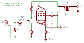
I think the operating principle is like the "Schadeode" I attached.
The first tube is sort of a voltage to current converter that balances
it's anode current against the current through Rfb i.e. the anode
feedback. The result is overall good linearity and low Zo.
This would seem to work better with a high Gm first tube,
or a high mu triode. This could be why the unbypassed Rk on
the first tube is important as well.
Cheers,
Michael
PS This doesn't have very good PSRR as is.
There are other more practical circuits; this
one is easy to understand but needs a very
well regulated and well filtered supply.
First, the nitpicking... G1 and G2 on both pentodes are reversed.
What is the OPT connection? Is it 230:9 or 230:18? It seems like
5K (230:9) is a more suitable load for the 807 than 1300 ohms.
I am working on a similar idea with a MOSFET and an 807 and
I thought 5K looked pretty good.
I would expect B+ on top of the CCS to need to be quite a bit
higher to accommodate peak anode voltage of 500 + peak
signal voltage of 150-200V or more so maybe 700-800 volts.
But maybe the 807 doesn't need to operate at quite 500V
for this signal swing?
I think the operating principle is like the "Schadeode" I attached.
The first tube is sort of a voltage to current converter that balances
it's anode current against the current through Rfb i.e. the anode
feedback. The result is overall good linearity and low Zo.
This would seem to work better with a high Gm first tube,
or a high mu triode. This could be why the unbypassed Rk on
the first tube is important as well.
Cheers,
Michael
PS This doesn't have very good PSRR as is.
There are other more practical circuits; this
one is easy to understand but needs a very
well regulated and well filtered supply.
Attachments
Also try reading this article from page 359 onwards.
http://www.clarisonus.com/Archives/TubeTheory/Schade 1938 Beam Power Tubes.pdf
It's quite illuminating.
http://www.clarisonus.com/Archives/TubeTheory/Schade 1938 Beam Power Tubes.pdf
It's quite illuminating.
Hi,
I built a very similar version to what you have suggested as my first valve power amp. I used a TT21 as the CCS and ran the B+ at about 800V. I eventually tried it with a MOT as a plate choke with just 350V This is the problem and why I wouldn't bother trying it, thats about 400V of absolutely wasted voltage which is just running up your electricity bill for no good contribution to the output power. It an absolute waste. Coupled to that it used to scare the hell out of me whenever I had to take the lid off and poke around. You can quite happily take a belt of 350V (though its certainly not advised) but your chances of survival with 800V is considerably reduced.
The MOT (Microwave Oven Transformer) loaded version had phase shift issues due I believe to the inadequate inductance. Real plate load chokes are more expensive than SE transformers.
My advise is get a reasonable cheap pair of SE transformers and build it as it was designed. I did this madness so that others didn't have to
If you want to build a cheap amp with Toroidals as outputs then I suggest that you build a PP amp. They will probably sound better, and needn't be terribly complicated to implement. I built a little EL82 headphone amp which I am currently using to drive my main speakers (because my main amp is on the bench), and if I optimised the output transformers I would rate it as the best amp I have built. Very simple, cheap and built without sand.
Shoog
- Status
- This old topic is closed. If you want to reopen this topic, contact a moderator using the "Report Post" button.
- Home
- Amplifiers
- Tubes / Valves
- RH807 CCS loaded