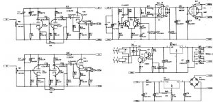
the front i think looks like the marantz m7 pre-amp. i think the values are the same too. But the cathode follower is using au7 instead of ax7. BUt the power supply looks pretty beef up. Looks like a series regulator with a differential stage used for error correction. The PS looks good, u should get regulation. What's B+ 280 vdc ? is this your first time building tube? because the m7 problem IMHO is too much coupling caps are used. Expensive and colours the sound. BUt it was my first tube i built in a kit. SO its a good place to start. AU7 makes a better cathode follower than ax7. IMHO this should sound not to bad due to good power supply. As i recall used the recommended volume pot 100k to 250K is going to be real loud. In the end i had to go for 250 K. Another irrating thing about ax7. LOUD with not much volume control. I see that there is a relay to delay the B+ should be good so no cathode stripping and the heater supply has a resistor after the lm317 good for limiting the current to the tube when powering up. Prolongs tube's life. May i suggest u utilize EH tubes electro harmonix. Cheap and good compared to NOS. Good luck in building it . Any other help needed do write
SCHEMATIC.
Hi,
Keep in mind that the first schematic you posted is a phono preamp, probably based around the Marantz pre as Nick suggests.
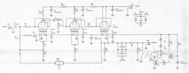
The second one looks something out of the Jadis cookbook and is a line preamp as is the third.
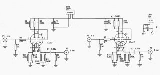
The third one would make more sense to me, it's simple and straightforward.
It will most likely be the best fit for a CD based system.
Looks a lot like a Foreplay but I can't be too sure, never seen the schematic for it but the desciption fits.
You'll need to add a volumecontrol to #s 2 & 3 though.
Cheers,
Hi,
Keep in mind that the first schematic you posted is a phono preamp, probably based around the Marantz pre as Nick suggests.
The second one looks something out of the Jadis cookbook and is a line preamp as is the third.
The third one would make more sense to me, it's simple and straightforward.
It will most likely be the best fit for a CD based system.
Looks a lot like a Foreplay but I can't be too sure, never seen the schematic for it but the desciption fits.
You'll need to add a volumecontrol to #s 2 & 3 though.
Cheers,
ok the second schematic IMHO really is not so good compared to the first one. AX7 don't make a good cathode follower. For good cathode follower action the formula is i think RP/ (mu+1) hence we see that ax7 has high mu 100 as well as high rp. So we not going anywhere with this tube. while 6922 has mu of 33 and rp of 3300 hence lowest example here. Au7 has mu 16-18 not sure and rp of 12000 i think again. hence the first schematic is better. Second never parallel tubes unless you are sure that they are matched plate to plate this hard unless you own a tube matcher like sofia. When they are not balanced the current is not shared properly and people say that they don't sound good. But they do have their advantages good for mc phono quieter, gm of the tube is double. More current capability. The second circuit seem to have a cap in the feedback hence there a phase shift induce by the cap. IMHO not a big fan of feedback in pre-amp circuits, furthermore a cap in feedback loop. Plus not a big fan of ax7 too, they are good to only 33 khz only and huge amount of gain. I currently using 6922 good to 2mHz configure something like the bottom circuit (figure 3) but without the cathode follower and bypass cap at the first stage. My output impedance is high around 16000 but i designed that way as I run short cables. I like the third one best looks like foreplay basic layout i think. Direct coupling between the two stages is good, saves money on coupling caps and don't add a phase shift to the sound. Regarding the transfomer size i not sure on the requirements of the heater supply for the tube rectifier. but for the b+ looks okay about max 60 mA draw. considering the tubes used should be fine ax7 around 1ma au7 around 3-8 ma depending on design. Design three is around 1 ma for the first stage, second stage should be more . unless you are playing around with different tube this transformer should be more. i run my 6922 at 10 ma per plate i like it hot get the rp down. IMHO AC heating sound better when i did it on my m7 2 ax7 and at7 for heater heating.
Thank you for the replies.
FIY, the second schematic is supposedly based on a Jadis JP200 preamp and the last one is based on an Audionote M7 preamp. I was convinced that the first one was also a line stage, not a phono preamp... I actually decided to build the first one based on the Marantz 7C because of the simplicity of having a good power supply section on the PCB already... it's a pretty expensive project (around us $500 ) using good quality components. We'll see how it sounds. The PCB's are of great quality though and were fairly inexpensive.. (around $30 each... The Jadis based one is actually one PCB per channel)
The only problem I've had so far is finding replacements for the transistors specified for the power supply (A42 and C2335). NTE makes replacement parts but I am not sure they are an exact match. Do you guys have any experience with these... recommendations?
PREAMP.
Hi,
It probably is one, I can't make out component values in most of the schematic and when the name Marantz 7C falls...I automatically think phono pre.
Sorry for the confusion caused.")
Hi,
I was convinced that the first one was also a line stage, not a phono preamp
It probably is one, I can't make out component values in most of the schematic and when the name Marantz 7C falls...I automatically think phono pre.
Sorry for the confusion caused.
Line stage
The first diagram is a line stage (the feedback doesn't have an RIAA network). Any old rubbish will do for the transistors. I would suggest MPSA44 for the HT transistors and BC549 for the LT transistors. Mind you, you will need to check that the pinout is the same as for the original. I wonder if the originals were actually MPSA42 (300V rather than 400V) and BC233S?
Give it a go, having a PCB makes life much easier. The circuit does seem to have rather more coupling capacitors tha is strictly necessary.
- Status
- This old topic is closed. If you want to reopen this topic, contact a moderator using the "Report Post" button.
- Home
- Amplifiers
- Tubes / Valves
- Schematic + PCB