I've been sorting through my 'plinker' tubes, trying to find creative uses for them -- especially the compactrons. I've already had some promising results using triple-triodes in John Broskie's three-section Aikido variation.
I have several sleeves of 31AL10's, a tube that initially looked extremely promising. These incorporate two dissimilar triodes and a beam pentode. Triode number 1 has a mu of 43, triode number two has a mu of 20, and the pentode has a plate maximum of 7 watts, with an Rp of 12k.
It first appeared that just two tubes would be necessary to make one complete stereo channel, using the two T1s as a voltage gain stage, the two T2s as the phase splitter, and the two pentodes as a push-pull output pair. Even better, four tubes required a total of 124 volts for the heaters, and only 400mA total heater current. A small isolation transformer would let all the filaments run in series straight off the wall socket. (Some would even claim that since the filaments are a purely resistive load, isolated from the signal path, that an isolation transformer wouldn't even be required -- just a fuse in each leg. I won't open that can of worms in this post).
Then I checked the pictorial of the tube in the datasheet, and everything came to a crashing halt. T2 and the pentode section share a common cathode. Rats! No way to use cap coupling or set up different bias currents for these two sections. The only configuration I can think of for directly-coupled cathodes is a long-tailed pair, and I don't see how this could be useful with two such dissimilar elements in a conventional circuit.
Any creative thoughts on using all three sections of these tubes to build a decent amp, or should they be relegated once more to the orphan pile? Thanks in advance for your comments.
Interesting problem. A couple options. T2 appears by far the better performer, hard tie the common cathode to ground and run fixed bias at the front end and output, T1 as splitter. Or do the splitting at the front end and use T1 as a CF driver, though T2 might not have the gain for the required feedback in pentode mode. Go triode output?
Second, more dangerous and therefore much more fun option. T2 and P2 look like they'll bias around the same G-K voltage. Cathode bias them with a single resistor and use T1 between them to flip phase such that P1's dynamic signal current through the common cathode resistor applies negative feedback directly to the cathode of T2.
Second, more dangerous and therefore much more fun option. T2 and P2 look like they'll bias around the same G-K voltage. Cathode bias them with a single resistor and use T1 between them to flip phase such that P1's dynamic signal current through the common cathode resistor applies negative feedback directly to the cathode of T2.
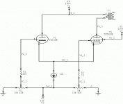
T2 and P2 look like they'll bias around the same G-K voltage.
Hmmm, ground the pentode grid and run cathode-coupled AB2....
- Status
- This old topic is closed. If you want to reopen this topic, contact a moderator using the "Report Post" button.