Hi there.
This question is for all the amp gurus out there. I need to decipher a tone stack from a picture, or few pictures. I know most of the resistor values and have an idea how they are connected but not 100% sure. Anyone with a keen eye and knowledge for out of the ordinary and strange tone stack circuits may help me to draw out the schematic for this amp. This is a Dallas Rangemaster 5412 model with tremolo.
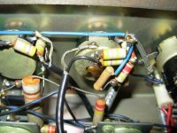
The tremolo section will be the next challenge by the way. I attach a few pictures from different angles so you can see and hopefully figure out the circuit. A brief description of the pictures;
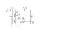
The decoupling cap that feeds into the tone stack is a 10nf and appears to connect to the treble pot's top connector. ( The top of the picture is actually the earth leg of the pot!) From where the 10nF connects, there is a 100k resistor connects to a junction of an unknown cap (it's leg looks like to connect to the earth leg of the treb pot) and a 220k resistor. The other side of the 220k resistor joins to another 220k resistor and perhaps to the centre wipe of the treble pot,(this is not sure though!). On the middle of the treble pot there are two 470k resistors, and they are seem to have been joined on the left hand side. This is where the next stage input shielded cable connects. Underneath that there seem to be a small ceramic type cap covered in wax? The topmost 470k resistor comes from the wiper leg of the bass pot through a shielded cable that is shielded (soldered to the treble pot's earth, top of picture.) The bass pot is on the right hand side, and it is the on/off switch at the same time.) It could be 1M or 500k, I am not sure. The bottom resistor of that pair connects to where? Also there is a ceramic cap coming from the top leg of the bass pot and joines to? (it could be the top leg of the treble pot, but this is only guessing.)
The sizes of the two ceramic caps indicate something like 3.9nF or 4.7nF - ish? The wax covered cap is more like the pF range, 100pF maybe?
These are all the components of the tone stack. Can anyone figure out how they could be connected and work? Any help would be greatly appreciated.
This question is for all the amp gurus out there. I need to decipher a tone stack from a picture, or few pictures. I know most of the resistor values and have an idea how they are connected but not 100% sure. Anyone with a keen eye and knowledge for out of the ordinary and strange tone stack circuits may help me to draw out the schematic for this amp. This is a Dallas Rangemaster 5412 model with tremolo.
The tremolo section will be the next challenge by the way. I attach a few pictures from different angles so you can see and hopefully figure out the circuit. A brief description of the pictures;
The decoupling cap that feeds into the tone stack is a 10nf and appears to connect to the treble pot's top connector. ( The top of the picture is actually the earth leg of the pot!) From where the 10nF connects, there is a 100k resistor connects to a junction of an unknown cap (it's leg looks like to connect to the earth leg of the treb pot) and a 220k resistor. The other side of the 220k resistor joins to another 220k resistor and perhaps to the centre wipe of the treble pot,(this is not sure though!). On the middle of the treble pot there are two 470k resistors, and they are seem to have been joined on the left hand side. This is where the next stage input shielded cable connects. Underneath that there seem to be a small ceramic type cap covered in wax? The topmost 470k resistor comes from the wiper leg of the bass pot through a shielded cable that is shielded (soldered to the treble pot's earth, top of picture.) The bass pot is on the right hand side, and it is the on/off switch at the same time.) It could be 1M or 500k, I am not sure. The bottom resistor of that pair connects to where? Also there is a ceramic cap coming from the top leg of the bass pot and joines to? (it could be the top leg of the treble pot, but this is only guessing.)
The sizes of the two ceramic caps indicate something like 3.9nF or 4.7nF - ish? The wax covered cap is more like the pF range, 100pF maybe?
These are all the components of the tone stack. Can anyone figure out how they could be connected and work? Any help would be greatly appreciated.
Attachments
Hi ,
here are my two penny words to it:
I have no schematic for this amp, but maybe a some helpful hints to find out how the tone stack is particulary wired.
Guitar amp tonestacks are not very distinguished between all the different brands. Look to a Fender , Marshall or Hiwatt schematic and you know what I mean.
Analyze the wiring in your amp and make a drawing of it, identify as many parts as possible and note their values into your drawing. Use a ohmmeter and if you have a capacitance meter for the C´s . The more you draw the clearly you see. When you luckily recognize all the parts of the tonestack you are in the ballpark.
your drawing will tell you now if something is miswired ore you can find the right solder lug for a loose end of a component.
Maybe this will help you anyway:
http://www.duncanamps.com/software.html
move down to : tonestack calculator.
there are different tone stack arrangements.
If you finished your schematic, put in here so we can help more
And I promise you even dallas amps are boiled with water.
regards from Hamburg
Wolfgang
Funker said:Hi ,
here are my two penny words to it:
I have no schematic for this amp, but maybe a some helpful hints to find out how the tone stack is particulary wired.
Guitar amp tonestacks are not very distinguished between all the different brands. Look to a Fender , Marshall or Hiwatt schematic and you know what I mean.
Analyze the wiring in your amp and make a drawing of it, identify as many parts as possible and note their values into your drawing. Use a ohmmeter and if you have a capacitance meter for the C´s . The more you draw the clearly you see. When you luckily recognize all the parts of the tonestack you are in the ballpark.
your drawing will tell you now if something is miswired ore you can find the right solder lug for a loose end of a component.
Maybe this will help you anyway:
http://www.duncanamps.com/software.html
move down to : tonestack calculator.
there are different tone stack arrangements.
If you finished your schematic, put in here so we can help more
And I promise you even dallas amps are boiled with water.
regards from Hamburg
Wolfgang
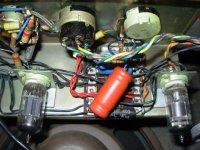
Thank you all for the speedy reply. However I didn't make it clear in my first post. I don't have this amp in front of me. If I did, I could draw out the schematic and gladly share it with you. All I have is a vague memory when I had a short time to poke my head inside this amp. (It belonged to a friend, but he sold it now.) At the same time he took a few pictures of the inside. For some reason I could only upload one picture to my post. Here is the other one from a different angle. Sorry for the pictures are low resolution, and I don't have higher res. ones available. My friend emailed me those long ago. If you want to see the rest of them just drop me a line and I will send them to you. They are probably the only pictures existing about this amp. I've looked lots of different tone stack solutions in 100 different amps. I am not an expert how it works though even though I was a Radio-Tv repair tech in the old days when even televisions were all valve affairs.
However this amp deserves all the chance to be saved from obscurity of the past.

Attachments
Hi ,
okay maybe I misunderstood your first post, so that you havn´t got this particulary amp not at yours and you have to solve the problem by only analyzing the picture s of it.
That could be a difficult task. You wrote the amp belonged to a friend of yours which had it already sold.
Why did you have now such a great interesting in that schematic. And why you didn´t it at a time as this amp where easy available to analyze it.
These Dallas amps seems to becomes very rare items as no information available in the internet. It is much more easier to get a schematic from secret military equipment as these amps probably classified to "confidential matter"
I´m also a radio TV-repairman and passed my examination in 1975, at this time the TV world was already transistorized. But after my examination I worked for a PA& Stage equipment Rental company where I had mainly to deal with Mixers , Power Amps and Lighting stuff. These company run also a amp repair shop specialized on Guitar amps. These workshop becomes more and more closer to me. In this time I had the opportunity and made an effort of it to grab as much as information as possible about the valve technology .
Today I install and maintain Telephone equipment. Valve technology is now a hobby. I build Guitar amps for friends and Hi Fi Amps for myself. I´m also Radio Amateur , my call is DF6ZC. I have also a collection of old military radios.
regards
Wolfgang
Funker said:Hi ,
okay maybe I misunderstood your first post, so that you havn´t got this particulary amp not at yours and you have to solve the problem by only analyzing the picture s of it.
That could be a difficult task. You wrote the amp belonged to a friend of yours which had it already sold.
Why did you have now such a great interesting in that schematic. And why you didn´t it at a time as this amp where easy available to analyze it.
These Dallas amps seems to becomes very rare items as no information available in the internet. It is much more easier to get a schematic from secret military equipment as these amps probably classified to "confidential matter"
I´m also a radio TV-repairman and passed my examination in 1975, at this time the TV world was already transistorized. But after my examination I worked for a PA& Stage equipment Rental company where I had mainly to deal with Mixers , Power Amps and Lighting stuff. These company run also a amp repair shop specialized on Guitar amps. These workshop becomes more and more closer to me. In this time I had the opportunity and made an effort of it to grab as much as information as possible about the valve technology .
Today I install and maintain Telephone equipment. Valve technology is now a hobby. I build Guitar amps for friends and Hi Fi Amps for myself. I´m also Radio Amateur , my call is DF6ZC. I have also a collection of old military radios.
regards
Wolfgang
Wolfgang.
We are from a very similar background. Back in those days I was always tinkering with valve amps, once I've built a stereo amp for my record player and it was just connected loose without any chassie and it nearly took up my bedroom floor space. Anyway my recent interest in valve amps came when I started to learn to play electric guitar. Then I found this amp in a skip. Yes it was the Rangemaster. Miraculously it worked fine, apart from the tremolo. You could hear the pulsating noise but it didn't effect the sound. I took it to a famous guitar shop to have it repaired, but the tech guy couldn't repair it. So eventually I've gone onto another project and needed the parts. So this amp provided this. I cannibalised most of it to build another amp. I drew out the power section, but not the preamp. Mistake. Then I've decided to rebuild it for my nephew. I found this guy who had this amp and he kindly sent me the pictures. Also managed to visit him and he let me look inside of this amp. However I didn't have a lot of time and I felt euphoric like a kid in a candy shop, way too excited to make a good drawing. I got most of the values for the preamp, and the tremolo, but I missed a few vital connection details, partly because I was too excited partly because some parts were concealed under the tremolo pot. (very crowded bit.) He sold the amp since so I have no chance to take another look. I guess I didn't realise at the time how wonderful these amps were, so now I am trying to rebuild one. The one I built for my nephew turned out to be very good, but with a different tone stack and a Vox AC10 like tremolo. The Vox's tremolo circuit had almost identical components in the circuit by the way, except it was cathode coupled. This amp had a different solution, maybe screen grid or anode coupled.
I will keep looking, someone must have one of these and willing to share some details.
Laszlo
Attachments
Funker said:Hi ,
here are my two penny words to it:
I have no schematic for this amp, but maybe a some helpful hints to find out how the tone stack is particulary wired.
Guitar amp tonestacks are not very distinguished between all the different brands. Look to a Fender , Marshall or Hiwatt schematic and you know what I mean.
Analyze the wiring in your amp and make a drawing of it, identify as many parts as possible and note their values into your drawing. Use a ohmmeter and if you have a capacitance meter for the C´s . The more you draw the clearly you see. When you luckily recognize all the parts of the tonestack you are in the ballpark.
your drawing will tell you now if something is miswired ore you can find the right solder lug for a loose end of a component.
Maybe this will help you anyway:
http://www.duncanamps.com/software.html
move down to : tonestack calculator.
there are different tone stack arrangements.
If you finished your schematic, put in here so we can help more
And I promise you even dallas amps are boiled with water.
regards from Hamburg
Wolfgang
What do you think Wolfgang?
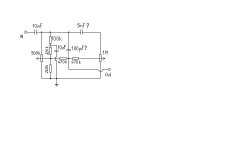
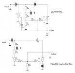
I drew out a schematic, the way I think they are connected. Would it work like this? Or anyone out there what do you think of this schematic?
Laszlo
Attachments
Hi Laszlo,
it may work but not in a way as I would exspect . Look at your drawing. Assume the wiper of the 500k pot is turned to the ground side. The audio on this point is grounded but there is still a signal path from the input via the 100p cap to the output. The small cap let only high frequencies passing to the output . So we have a low cut .The other way round eg the slider is up to its signal side, there will be an increasing amplitude of the lower components of th signal. The 10n cap form a low pass filter with the 100k and the 220k R´s parallel. But the attenuation depends hardly by the Ri of the driving circuit. It is not an ideal basscontrol. With a low Ri of the driving stage it will be louder but not only the bass.
Similar to the other potmeter with the wiper to its ground, there is no attenuation of the treble the 100 p cap has a quite low xc at it. With the wiper at the high side , it is nearly the same like the other potmeter. The whole signal increase due to the low xc of the 5n cap at low frequencies. ( xc of the 5n cap is 636k at 100Hz) .
I believe there is a wiring fault in the circuit or you did somewhat wrong by tracing the circuit. The circuit should be established like either the E-series or the James circuit as they are illustrated in the Duncan´s tone stack calculator. Good luck by tracing the wiring.
So now its time for a cool and tasty beer! We now 2110 h local time!!
regards
Wolfgang
Funker said:Hi Laszlo,
it may work but not in a way as I would exspect . Look at your drawing. Assume the wiper of the 500k pot is turned to the ground side. The audio on this point is grounded but there is still a signal path from the input via the 100p cap to the output. The small cap let only high frequencies passing to the output . So we have a low cut .The other way round eg the slider is up to its signal side, there will be an increasing amplitude of the lower components of th signal. The 10n cap form a low pass filter with the 100k and the 220k R´s parallel. But the attenuation depends hardly by the Ri of the driving circuit. It is not an ideal basscontrol. With a low Ri of the driving stage it will be louder but not only the bass.
Similar to the other potmeter with the wiper to its ground, there is no attenuation of the treble the 100 p cap has a quite low xc at it. With the wiper at the high side , it is nearly the same like the other potmeter. The whole signal increase due to the low xc of the 5n cap at low frequencies. ( xc of the 5n cap is 636k at 100Hz) .
I believe there is a wiring fault in the circuit or you did somewhat wrong by tracing the circuit. The circuit should be established like either the E-series or the James circuit as they are illustrated in the Duncan´s tone stack calculator. Good luck by tracing the wiring.
So now its time for a cool and tasty beer! We now 2110 h local time!!
regards
Wolfgang
Wolfgang.
Very good work, thank for all the effort. I did try out the circuit and realised that it doesn't work, especially the treble control. So I went back to the pictures and there is a possibility that between the two 220k's common point and the middle wiper of the treb pot the wax cap should connect like in this picture below.
I will try it out tonight to see if it works.
Attachments
Hi Laszlo,
Id burn some brain cells with this kind of tone control and made my modifications as I thought it could be arranged like this (see attachment) It is, of course a peculiar circuit far away from others.
My rearrangement using all of the existing parts and noone is left over.
regards from Hamburg
Wolfgang
Attachments
Funker said:Hi Laszlo,
Id burn some brain cells with this kind of tone control and made my modifications as I thought it could be arranged like this (see attachment) It is, of course a peculiar circuit far away from others.
My rearrangement using all of the existing parts and noone is left over.
regards from Hamburg
Wolfgang
Thanks Wolfgang.
I really appreciate all solutions. However I would like to stick to the original as possible. Looking at your drawing, it looks more like a bandaxall circuit, that countless amps use, perhaps with not exactly these values or extra component. Like I said before, this circuit has to work based on the picture. There are not many variation as how to actually connect the part together. Some connections are obvious from the image. Some are either this or that.
Last night I've rebuilt it like the above drawing and finally it started to behave as it should and as I remember when I had the opportunity to listen to the original amp. When you turn on full the treble it rolls off the bass and the sound high, and when you turn on the bass it does the job too. All I have to do now is to work out the best values of the three unknown capacitor values by playing with different ones and listen to the sound. I'm afraid my electronics knowledge is not up to calculating the frequencies, unless you know how to do it and let me know the formulas.
By the way what program did you use to draw your schematic?
Hi Laszlo,
as you wrote there are not much possible variations , but the pictures are not the same like to have the amp on the bench.
The circuit is only a little bit like baxandall, the latter has no low pass filter in it. (ref. obove picture R6, C7,R7)
The behavior of all these passive tone controls are deeply depends on the in/ output impedances of the associated circuts.
You wrote you build the circuit of the obove picture. Did you build your or mine version?
yes I can calculate the tone control component values by given roll off frequencies and impedances, but not from memory, I have to use my old radio education books for this. Due to them they are written in german I found and english link to the formulas.
Look at this:
http://www.schmarder.com/radios/tech/tone.htm
I use splan for my drawings , look here:
http://splan.softonic.de/
I is a german software and I don´t know if an english version are available.
regards from Hamburg
Wolfgang
Hi, me again,
I found an english link for splan,
look at this:
http://www.abacom-online.de/uk/html/produkte.html
regards from hamburg
Wolfgang
I found an english link for splan,
look at this:
http://www.abacom-online.de/uk/html/produkte.html
regards from hamburg
Wolfgang
Funker said:Hi, me again,
I found an english link for splan,
look at this:
http://www.abacom-online.de/uk/html/produkte.html
regards from hamburg
Wolfgang
Thanks again Wolfgang.
I get stack in right away.
Cheers
Laszlo

- Status
- This old topic is closed. If you want to reopen this topic, contact a moderator using the "Report Post" button.
- Home
- Amplifiers
- Tubes / Valves
- Tone Stack Challenge