The TVA10 is a late 70s nightmare waiting to happen. I had one once. It oscillates if you leave its input open-circuit. It oscillates if you leave its output open-circuit. Each time, the EL34s glow red to let you know. It runs hot, so there are various things that could be dying. Have a look inside, and look for bulges on the ends of electrolytic capaitors.
TRANS VOLTAGE AMPLIFIER?
Hi,
Oh dear...this amp is one example of those designs that gave valve amps a bad rep.
While it can sound fine, in the hands of the unaware it has been known to burn out its OPTs due to parasitic oscillation.
Sorry, but I feel this is one amp one shouldn't own.
Cheers,")
Hi,
Oh dear...this amp is one example of those designs that gave valve amps a bad rep.
While it can sound fine, in the hands of the unaware it has been known to burn out its OPTs due to parasitic oscillation.
Sorry, but I feel this is one amp one shouldn't own.
Cheers,
oh my god! sound like a nightmare for me ! !
i got a sch and i not sure the voltage ....... hope u guy can help me
when i measure the HT i only got 408 v and the sch show me 500 v !
http://www.audiocircuit.com/9120-va...ial/MichaelsonAndAustin-MAA/9120CMMAA-SCH.htm
i got a sch and i not sure the voltage ....... hope u guy can help me
when i measure the HT i only got 408 v and the sch show me 500 v !
http://www.audiocircuit.com/9120-va...ial/MichaelsonAndAustin-MAA/9120CMMAA-SCH.htm
Low HT
There are two main possibilities.
The 600uF capacitors were rather nasty RS types that lived near to the (hot) mains transformer. If they have gone leaky/low value, the HT will be low, and there will be hum.
The bias supply to the output valves is failing, and causing the output valves to draw too much current. Check the voltage on the grids of each output valve, it should be about -45V.
Finally, could you please type in the Queen's English? I don't imagine your tutors accept work typed in the style of a mobile phone text message, so don't use it on an international noticeboard. Replies to questions take time, and although everybody has tolerance for posters for whom English is not their first language, there is no excuse for a student in Britain to be sloppy.
EC8010
I found the -ve bias caps is leaking and i change it and the hum is gone ! But went i turn the volume to 9 o'clock the sound start distort / broken ! The polarity on the -ve is connected right or wrong ? I've check the voltage .. Bias -44V HT 450V ..please help. thank !
ps thank for ur advice. i'll take into account
Anyone interested in the TVA-10?
I also have acquired a TVA-10, but was not not lucky enough to have been given it, like the previous poster
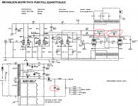
I also have an issue with the electrolytic that is part of the power supply, ringed in the previous post. Why is that capacitor rated at 500V? Bias is set at 45V, and a 500V capacitor is a bit more specialised (and pricey) for replacement.
However, there are two more 22uF electrolytics, both 500V, used as part of the push-pull output stage, where B+ is set to 500V. That seems a bit marginal to me - any views?
Schema is attached. I would be grateful if someone could explain how the output stage is working. Is it just a separate transformer winding for GFB? Is this a common solution to cross-link the anodes and screens?
I noticed this amp got some bad press further up the thread, but I think that that is based on another M&A design which did have a reputation among fire departments.
Before I replace the 3 22uF electrolytics, the sound is quite 'mushy' and not at all a distinct sound stage, as I would expect with a tube amp. However the low frequency response is pretty good.
Anyway, wondering how much effort should be expended on this, or whether I should cut my losses and build a more standard design on the old chassis.
I also have acquired a TVA-10, but was not not lucky enough to have been given it, like the previous poster
I also have an issue with the electrolytic that is part of the power supply, ringed in the previous post. Why is that capacitor rated at 500V? Bias is set at 45V, and a 500V capacitor is a bit more specialised (and pricey) for replacement.
However, there are two more 22uF electrolytics, both 500V, used as part of the push-pull output stage, where B+ is set to 500V. That seems a bit marginal to me - any views?
Schema is attached. I would be grateful if someone could explain how the output stage is working. Is it just a separate transformer winding for GFB? Is this a common solution to cross-link the anodes and screens?
I noticed this amp got some bad press further up the thread, but I think that that is based on another M&A design which did have a reputation among fire departments.
Before I replace the 3 22uF electrolytics, the sound is quite 'mushy' and not at all a distinct sound stage, as I would expect with a tube amp. However the low frequency response is pretty good.
Anyway, wondering how much effort should be expended on this, or whether I should cut my losses and build a more standard design on the old chassis.
Attachments
Yes, that 'lytic in the bias supply is well overdressed. A 200 Vdc rating is sufficient.
Yes, those 22 µF/500 V 'lytics are marginal. Better get 550 Vdc ones.
No, those multiple primaries in the OT's aren't for CFB. We see that unity coupled amplifier design, according to Gordon Gow's and Frank McIntosh's patents.
Best regards!
Edit: Where are you located? I'd be interested in your appliance in it's present state.
That output stage is peculiar. It seems to have two different types of positive feedback. The DC feedback to the screen grid will tend to unbalance the output - which seems strange. Meanwhile, the AC feedback to the cathode will tend to balance the output - yet bring the risk of oscillation. I have no idea what the designer thought he was doing.
Well, the OTS' primaries are wound trifilarly. The lowest section at the bottom serves for NFB, the middle one as the cathode part and the upper one as the anode part of the load.
Those 22µF's can even be found in McIntosh designs, e.g. in the MC-3500/MI-350 (with a value of 10 µF here). Their positive leads might be swapped to the other ends of the 470R's, hence converting them to screen grid decoupling caps to ensure true pentode mode.
Best regards!
Those 22µF's can even be found in McIntosh designs, e.g. in the MC-3500/MI-350 (with a value of 10 µF here). Their positive leads might be swapped to the other ends of the 470R's, hence converting them to screen grid decoupling caps to ensure true pentode mode.
Best regards!
Edit: Where are you located? I'd be interested in your appliance in it's present state.
Hi Kay Pirinha, Thanks for your very helpful insight!
I'm based in Stockholm. I have a read various views on this amplifier, and it does seem to split the audience. There is another amp - I think it s the TVA-1 - that did have some issues, and that colours opinions, however, looking under the hood, the amp is built to a budget, and that can lead to unreliability.
I am hopeful that if I upgrade the electrolytics a bit - they are over 30 years old now - then I can address this 'mushiness' in the sound. On the positive side, the transformers are meant to be top notch (Partridge, supposedly) and there is nothing too exotic in its construction. As I learn more about the intricacies of designing tube amplifiers, it ought to be within my capabilities to keep it running, so I'l probably hang on to it for now.
Cheers!
Well, the OTS' primaries are wound trifilarly. The lowest section at the bottom serves for NFB, the middle one as the cathode part and the upper one as the anode part of the load.
Those 22µF's can even be found in McIntosh designs, e.g. in the MC-3500/MI-350 (with a value of 10 µF here). Their positive leads might be swapped to the other ends of the 470R's, hence converting them to screen grid decoupling caps to ensure true pentode mode.
Best regards!
Hybrid connection that is half anode output and half cathode output?
I have a read various views on this amplifier, and it does seem to split the audience. There is another amp - I think it s the TVA-1 - that did have some issues, and that colours opinions, however, looking under the hood, the amp is built to a budget, and that can lead to unreliability.
Hi.
I have succesfully also repaired a TVA-10 a couple of years ago.
YES - it was the TVA-1 that were exploding. It was designed by M&A themselves, whereas the TVA-10 is designed by Tim De Paravincini and did not explode.
Check out the schematic for E.A.R. 509... it is identical apart from the output tubes and the transformer ratios!
I am hopeful that if I upgrade the electrolytics a bit - they are over 30 years old now - then I can address this 'mushiness' in the sound. On the positive side, the transformers are meant to be top notch (Partridge, supposedly) and there is nothing too exotic in its construction.
The well functioning amp has no mushiness at all - it has a super tight bass and rich detailled mid an highs. Good luck.
Hybrid connection that is half anode output and half cathode output?
Yes. The McIntosh/Gow patent calls it Unity Coupling.
Best regards!
Hi.
I have succesfully also repaired a TVA-10 a couple of years ago . . .
Hi Nrik,
Out of interesr, what fault were you fixing?
What output tubes did you have?
Rgds, Richard
Hi,
Just happen to come across this tread.
Found a TWA-10 in a dumpster, in the early 90ties IIRC. One of those "I can't believe my eyes" moments. There were 2 faults with it.
1. The mains switch were shot - easily fixed.
2. The second tube V2a/b is marked as ECC83 on the schematic. If you check the voltages noted in the schematic, on the anode of V1 (65V) and the cathode of V2 (70V), you see that this will not work with an ECC83. I don't know what the correct tube should be, but I used an ECC82 for V2 and the amp worked again.
This amp opened my eyes/ears to "tubes". Still have it, but unfortunately only collecting dust.
/Urban
- Status
- This old topic is closed. If you want to reopen this topic, contact a moderator using the "Report Post" button.
- Home
- Amplifiers
- Tubes / Valves
- Michaelson & Austin TVA 10