Hi guys
I have made a couple of variable anode CCS sources. One cascode enhancement Mosfet LED biased of mine, and one Jung's LM317 10M45S cascoded. I am running experiments on my 6V6 trioded line pre. My B+ is 330V regulated and there is a capacitor bypassed 680R cathode resistor installed. I measured much better THD at the same bias point where the previous 5K resistive load was sitting (22mA). Sounded dynamic and clean, but in the long run I miss the previous tamer but more natural tone. It got more SS taste, and it got a bit of more hiss on my 95db speakers. When I took it down to 15mA, it backed up on hiss and SS tone, but still the same impressions. I wanna retain the dynamic and THD gains, but bring back some triode tone. I guess that valves can be pushed a bit with anode CCS and hiss if not lower current than previously with resistor is chosen? OK, the Mu is pushed now, but I have got more hiss compared to gain.
It reminded me of when running a noval hotter until it starts to simply hiss. Anyway, that is why I wanna listen to the Anti-triode before I go back to resistor loading. How it can be practically done best? I mean, just put two resistors between CCS and anode, and tap off from the center for output? OK then, is there a formula to calculate, given the B+, freely chosen CCS current, and given Rk as I described above?
EDIT: Here is the chart of 6V6 trioded. Suggestions for anti-triode?
Attachments
Nelson's Pass' Aleph may be your best bet.
It can be reconfigured as an MJK Anti-Triode.
Which makes it a lot less complicated than
Nelson's way, and direct coupled as well.
I've omitted the gate pullup bootstrap off the
source of the MOSFET for clarity. But with it,
you can get with within a volt or two of the
upper rail.
10M45S needs 10 or 15 volts standing on it.
Gate capacitance and VGS-ON an unknown.
Other than that, it still seems to work.
Aleph gets around both those issues.
Attachments
Thanks kenpeter. 10M45S is enhancement mode that includes an error amp so it stays on like a Depletion mode Mosfet. I have to use my IRFPs. Something that bugs me a little is that I have to resort to one Vbe CCS non cascoded. The D.Self bootstrap cap enhances the lot by positive feedback of course. I was hoping there is a clever way with the already made couple of CCSs that I have, but I must draw a new one most probably...
Might use a similar circuit inside? They don't say.
Acts like -5VGKon, so it can't be an Aleph emitter
drop. Maybe another enhancement MOSFET?
Aleph is pretty consistent in the emitter coupled
on voltage. And the Base follows the Emitter, so
the impedance isn't real low like you'd think.
I've been playing with it a bit lately. Pretty sure
I'm driving Nelson crazy over on that side of the
forum.
Turn his junk inside out and make current mirrors
and other wierd thingies... Off deep end as usual.
Here is what works like a charm; actually it is a gyrator. You may use MOSFETs here, or at least one on top to increase voltage divider's resistance and decrease capacitance needed.
It does not provide a constant current on DC. Actually, on DC it provides a constant voltage, but on AC it's dynamic resistance is huge.

It does not provide a constant current on DC. Actually, on DC it provides a constant voltage, but on AC it's dynamic resistance is huge.
kenpeter said:That is absurdly cool!
I'm sure you've shown it before, but I only just now "got" it.
My pleasure!
")
Wavebourn said:Here is what works like a charm; actually it is a gyrator. You may use MOSFETs here, or at least one on top to increase voltage divider's resistance and decrease capacitance needed.
It does not provide a constant current on DC. Actually, on DC it provides a constant voltage, but on AC it's dynamic resistance is huge.
I have a hunch that this one escapes the monotonous CCS anode sound. Nice one!
kenpeter said:Now if you just flip it upside down and make an anti-triode...
I have no clue if this actually works or not...
We have to simulate it. Is it possible that C1 must be going to B+ ?
Wavebourn said:It does not provide a constant current on DC. Actually, on DC it provides a constant voltage, but on AC it's dynamic resistance is huge.
Maybe its constant DC current fed from very low impedance that makes tubes hiss on bias points that they were behaving themselves previously loaded with resistors? The most perfect a CCS is, the more the tubes get excited. Especially if its a BJT source.
salas said:
I have a hunch that this one escapes the monotonous CCS anode sound. Nice one!
Thanks!
Actually, this one escapes constant flow of anode voltage and it's dependence on tube brand, age, and filament power fluctuations.
This gyrator one you posted mimics a large coil. In such a way tubes used to be loaded back in the days they got conceived, whenever enough B+ was not available. Sounds like a more natural way. I will try to simulate one using the P Mosfets and LEDS that are already mounted on my CCS boards. I guess that will be the fastest and most economic way to listen to the gyrator load. I will post my contraption schematic before I will tweak those perfboards. Will you inspect Wavebourn?
Attachments
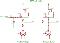
Here are SEPP or series push-pull circuits using cascode depletion mode
MOSFETS. The difference between these and CCS is that these will
drive symmetric current, push and pull so to speak, while retaining the
harmonic signature of the triode.
A vanilla CCS will only source up to it's constant current into the load,
where in a practical circuit the anti-triode will source almost 2X the
quiescent current, in exact opposite to the triode's low-current
half-cycle. This is analogous to the choke's energy storage.
It's good to provide some extra quiescent current so the anti-triode
doesn't get starved and clip on the triode's high current half-cycle.
In a line amp this is less of a problem than for a parafeed output stage
or power grid driver. (for a power grid driver I'd arrange it more like
a mu-follower anyway because it has asymmetric drive requirement)
There is a constant voltage variant. It doesn't matter really how you
develop the fixed voltage. It can be used with fixed bias because it
can regulate the plate voltage.
The constant current variant is good for low Rp, high gm tubes in
fixed bias to regulate the op point.
Cheers,
Michael
Attachments
- Status
- This old topic is closed. If you want to reopen this topic, contact a moderator using the "Report Post" button.
- Home
- Amplifiers
- Tubes / Valves
- Anti-Triode SEPP, how to do best?