Salas said:Does the 10X original resistor gives problems with noise rise?
No, it is shunted on AC.
revintage said:Also noted the two bypass caps interact so check this. Maybe Wavebourn can shade some light on this?
I use big cathode bypass, 1000uF Silmic II usually.
Questions
A couple of (possibly stupid) questions:-
Was looking at IRF9610 this afternoon. It looks like a pretty high speed device. Won't it have an increased possibility of instability? Will 220r gate stoppers be sufficient?
There wouldn't be any unwanted interaction with this circuit if I use LED biasing on the cathode, would there? (currently designing for 5687, and soon for 6n6p. DHT to follow, possibly1j6g)
Salas, you said way back in the thread "It is not like changing points by varying a CCS. B+ choice is the key so to hit the bias you look for."
Could you (or someone else who understands this circuit) please explain a bit more clearly? Eg, when you adjust the trimpot, what will actually happen to the voltage and the current?
Originally, you said the circuit would hold the anode at about 1/2 B+, but a number of changes to it since then will no doubt have changed that. Is voltage drop proportional to the voltage divider formed by 10meg and trimpot?
(Sorry, told there might be some stupid questions.)
Set anode voltage by a trimpot, and current by a cathode resistor. Instead of a bottom MOSFET you may use a PNP BJT. I don't understand why you want to run a LED biasing current through cathode resistor.
Edit: sorry, I misunderstood about LED cathode biasing. Yes, it is fine to bias cathode by LED in terms of it's low dynamic resistance, but for longer tube life resistor shunted by a cap is preferable. Your choice.
Edit: sorry, I misunderstood about LED cathode biasing. Yes, it is fine to bias cathode by LED in terms of it's low dynamic resistance, but for longer tube life resistor shunted by a cap is preferable. Your choice.
Re: Questions
There exist no stupid questions, only silly assumptions if we don't dare ask. Fire away, I ask basic stuff all the time!
For IRF9610 I don't know yet, my tests were done with IRFP9240 which were pretty happy with 220R. I guess you can start with 1k to be on the safe side.
For the other questions, Wavebourn covered. Respect to Anatoly, its his idea, I only did it with cascoded Mosfets.
hihopes said:A couple of (possibly stupid) questions:-
Was looking at IRF9610 this afternoon. It looks like a pretty high speed device. Won't it have an increased possibility of instability? Will 220r gate stoppers be sufficient?
There exist no stupid questions, only silly assumptions if we don't dare ask. Fire away, I ask basic stuff all the time!
For IRF9610 I don't know yet, my tests were done with IRFP9240 which were pretty happy with 220R. I guess you can start with 1k to be on the safe side.
For the other questions, Wavebourn covered. Respect to Anatoly, its his idea, I only did it with cascoded Mosfets.
Instead of a bottom MOSFET you may use a PNP BJT.
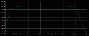
I simmed with a MJE350 at the bottom and, as suspected, get indications of better bandwith.
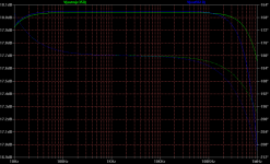
Another option could be to also use a P JFET at the top. Doesn´t change bandwith though.
I don't know if anyone here has had a close look at the datasheet for IRF9610. While the capacitance is a lot less than 9240, there is quite a steep curve to it (all 3 capacitances), which only really flattens out at about -25v. I would think that, unless the device has about 30v across it, the modulation of the anode's sinusoidal output would cause extra 2nd harmonic distortion in the mosfet. Perhaps BJT's (particularly in the "lower" position would be a good idea for this reason also.
.
.
Yes, it is fine to bias cathode by LED in terms of it's low dynamic resistance, but for longer tube life resistor shunted by a cap is preferable. Your choice.
Longer tube life? Do you mean because of the inability of the bias voltage to adjust itself as the tube ages and starts getting gassier?
I missed this thread before, sorry. Otherwise I would have commented on your very clever circuit. That's an interesting variation on a CCS. I use gyrators for active crossovers, but never have as a plate load. Excellent idea!
hihopes said:I don't know if anyone here has had a close look at the datasheet for IRF9610. While the capacitance is a lot less than 9240, there is quite a steep curve to it (all 3 capacitances), which only really flattens out at about -25v. I would think that, unless the device has about 30v across it, the modulation of the anode's sinusoidal output would cause extra 2nd harmonic distortion in the mosfet. Perhaps BJT's (particularly in the "lower" position would be a good idea for this reason also.
.
I just used IRFP9240 since it was handy, despite its limited bandwidth due to higher Ciss. At least it did not oscillate. Lars has seen more in to it and said that 9610 simulates a lot better. Maybe he can help more with your question if had run Fourier for both Mosfets too.
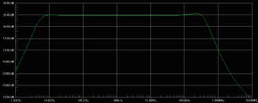
Simulated bandwidth with 9240 and 12AU7.
Attachments
- Status
- This old topic is closed. If you want to reopen this topic, contact a moderator using the "Report Post" button.
- Home
- Amplifiers
- Tubes / Valves
- Anti-Triode SEPP, how to do best?