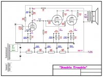
Playing around with some more junkbox parts, I came up with the attached schematic.
I have read all I can about NFB but I am still confused. Look at the feedback loop I put in the schematic. My assumptions were this:
Max swing in the positive direction thru the OPT primary is ~94V.
so at the secondary it is ~4V? (94/25 (turns ratio)
The ratio of the 100K FBR to 1K1 RK is .011 so I see about .044V to the cathode? If the gain without Feedback is ~50. What is the amount of gain I am loosing? So for say of argument if I didn't lose ANY gain would I see a negative swing on the output of -2.2V?
I am sorry if this seems like a total NOOB question but I just can't get my hands around the NFB thing. The distortion is already pretty low but what I am trying to do is experiment with the feedback. Once I understand it I can then play with different bias points to increase power and use the feedback to "fix" the increase in distortion.
BTW, the .22uF cap I was thinking will reduce the feedback below about 1Khz.
Ignore all the poles in the PSU I like to play with resistors & capacitors LOL")
I have read all I can about NFB but I am still confused. Look at the feedback loop I put in the schematic. My assumptions were this:
Max swing in the positive direction thru the OPT primary is ~94V.
so at the secondary it is ~4V? (94/25 (turns ratio)
The ratio of the 100K FBR to 1K1 RK is .011 so I see about .044V to the cathode? If the gain without Feedback is ~50. What is the amount of gain I am loosing? So for say of argument if I didn't lose ANY gain would I see a negative swing on the output of -2.2V?
I am sorry if this seems like a total NOOB question but I just can't get my hands around the NFB thing. The distortion is already pretty low but what I am trying to do is experiment with the feedback. Once I understand it I can then play with different bias points to increase power and use the feedback to "fix" the increase in distortion.
BTW, the .22uF cap I was thinking will reduce the feedback below about 1Khz.
Ignore all the poles in the PSU I like to play with resistors & capacitors LOL
Attachments
Hey Kev!
Thanks, I was thinking that but like I said this whole NFB thing is confusing to me. So with the unbypassed Rk the calc's change. Since the gain of the AX7 stage is now only about 27?
So now about 1.1V? on the output of the AX7?
How do I calculate the feedback's effect on Gain?
And am I even on the right track?
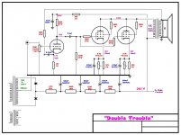
kmaier said:It won't work... you have to remove the cathode bypass capacitor on the input stage or it simply grounds out the feedback signal, i.e., no feedback.
Regards, KM
You meant like this correct?
Attachments
kmaier said:Hi CC,
Hint.... RC30 pages 38-40 cover inverse feedback, aka negative feedback.
Regards, KM
DUH!
Thanks for the hint! I didn't make the "mental" connection of Negative Feedback and Inverse feedback. Actually isn't "Inverse Feedback" the more appropriate name?
Ok,
I read through the RCA manual and I STILL do not understand FeedBack. They explain it with a voltage divider & cap based upon a tranformer coupled section and take the feedback from the primary of the OPT.
Can anyone explain the basic method for calculating feedback taken from the secondary of the OPT and fed back to the input section?
or a bit alike'n
the nfb works by effectively taking a negitive of the wave form after it has
been through the amp (from the out-put transformer), and then putting it on the
wave form at the start of the amp.
with this you then get the source aborbing the amount of negitive feed back
which is in the image of the source.
so you still get some of the source
BUT IT WILL CARRY WITH IT through the amp THE NEGITIVE OF THD AND AN HASH SOUND THAT THE AMP
WOULD OTHER WISE MAKE
and this will greatly reduce the distortion through out the amp if set up
right...i think ?
- Status
- This old topic is closed. If you want to reopen this topic, contact a moderator using the "Report Post" button.
- Home
- Amplifiers
- Tubes / Valves
- Some Help with Feedback Please!