Hi guys,
I'm developing a new hybrid amp, a tube input stage driving a pure class A mosfet output stage.
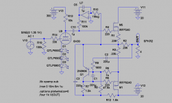
Actually only an idea, but HERE is the first schematic.
I have also opened a thread HERE
I have a question for you tube gurus.
The feedback is taken from the output and then reported back to the tube grid input: would it work?
Any issue you can see?
I've never seen a feedback scheme like this before, so I'm not sure it will work fine.
I know the source (My CD unit) would see a not constant impedance, but this should not be a problem, I think.
Any other idea for the feedback?
I could use a long tail pair, but I would prefer to use a single triode on the input.
Any other input topology which could be suitable (one tube, please)?
Ciao,
Giovanni
I'm developing a new hybrid amp, a tube input stage driving a pure class A mosfet output stage.
Actually only an idea, but HERE is the first schematic.
I have also opened a thread HERE
I have a question for you tube gurus.
The feedback is taken from the output and then reported back to the tube grid input: would it work?
Any issue you can see?
I've never seen a feedback scheme like this before, so I'm not sure it will work fine.
I know the source (My CD unit) would see a not constant impedance, but this should not be a problem, I think.
Any other idea for the feedback?
I could use a long tail pair, but I would prefer to use a single triode on the input.
Any other input topology which could be suitable (one tube, please)?
Ciao,
Giovanni
Now is clear.ray_moth said:What Jan says is correct. The NFB ratio will be totally dependent on the impedance of the source. Much better to use the more conventional approach of applying the NFB to the triode's cathode, at the top of R18.
Obviously I can't apply NFB in the circuit I drawn, because the output is in phase with the tube anode.
I have to add a second tube stage or use a different approach, like a long tail pair, where I have an inverting input.
Or, another approach would be to have no feedback at all.
But I don't like this approach with this amp.
Thank you very much.
I think you're wrong about this. The output may be in phase with the tube anode, but the anode is 180 degrees out of phase with the grid and cathode, so it seems to me that the NFB should work as you have drawn it.Obviously I can't apply NFB in the circuit I drawn, because the output is in phase with the tube anode.
ray_moth said:
I think you're wrong about this. The output may be in phase with the tube anode, but the anode is 180 degrees out of phase with the grid and cathode, so it seems to me that the NFB should work as you have drawn it.
Ray is quite right, and adding a 47K resistor in series with the input will give you an inverting power amplifier with a somewhat higher input impedance (about 56K or so) because the T network in your feedback loop is attenuating the feedback signal by more than 40dB and there is insufficient loop gain available for this to be effectively closed loop operation.
I would either replace all three of those resistors with a single 150K resistor which would give you a closed loop gain of slightly less than 10dB or see below. ( Remember the open loop gain is not very high as the mu is only 22.) 10dB of voltage gain would give you about 16dB of feedback - note that the source impedance should be low relative to the input resistor I mentioned in order to get the gain required.
A properly chosen T network for setting feedback ratio would allow you to use lower values of resistance and set any feedback ratio you wanted within reason.. Using Rin of 47K I would make R22 = 47K, R19 = 1K, and R20 = 5.1K . This would give you about 12dB of closed loop gain.
Note that as drawn your current source load in the 6N6 plate circuit is drawn incorrectly - the source should go towards the supply and drain towards the plate. You might want to ask SY for advice on a better current source as the AC performance of this one is not going to be too good for a variety of reasons. ( reverse transfer admittance, mediocre linearity, poor HF performance, relatively low resistance.) I think you want a cascode type of source here.
Hi again,
As I tried to explain in the other thread you will not need any NFB if you use the output device as sourcefollower.
I simmed the attached circuit with 6H30 as driver. It is not far from 6N6 and its just a matter of taste and biasing......
You will probably get 30W into 4ohms at ca 1% THD without NFB with the modulated CCS at the output. Seems like damping factor is ca 20 rel. 8ohms.
Probably no CCS is needed on top of the driver either. The main advantage with CCS could be that you could lower in B+ from 300V to just above 150V.
Attachments
The CCS on top of the driver is there exactly for that reason, to lower B+ and save power (actually the amp will be a little oven, and to save even 10Watts of energy is not too bad).
150V is exactly the value I had in mind, cause the opewrating point I choosen for the 6N6P is around 120V@22mA.
From now on, I think I will follow only the pother thread, started before this one, cause these two threads are confusing me.
Ciao
150V is exactly the value I had in mind, cause the opewrating point I choosen for the 6N6P is around 120V@22mA.
From now on, I think I will follow only the pother thread, started before this one, cause these two threads are confusing me.
Ciao
- Status
- This old topic is closed. If you want to reopen this topic, contact a moderator using the "Report Post" button.
- Home
- Amplifiers
- Tubes / Valves
- Feedback question