") ?
?With the 6080 cathodes connected to halfway points of the voltage doublers and the plates connected to the full voltage doubler, there is DC current thru the T? xfmrs (unbalanced load on the voltage doublers). The xfmrs are going to get hot.
Biasing of the 6080's appears to be auto-bias by R11 and R18.
Biasing of the 6080's appears to be auto-bias by R11 and R18.
circlotron
I noticed the bias voltage as half of the doubler voltage with the return through R2 and also the supply of the splitter tubes both crossing through the output transformer and tough in opposite direction innbalance can easily occur especially with three 6080 in parallel and this would defy the whole purpose of the circlotron which is not suppose to pass DC through the load This was the reason I asked for the bias adjustement .
monyse
With R16 at 100K and R12 at 360K, it looks like auto-biasing by R11 will be around 2/3 control and ground reference thru R2 around 1/3 control (which as you say, goes thru 1/2 the V multiplier.). So line voltage will affect biasing for sure. I could see where some control like this could be useful to keep the 6080's regulated versus line voltage, but this seems like too much effect.
The floating supply connections to R3 and R17 may be intended as bootstrapped (CCS like a'la McIntosh) ) loads for the 6AU6's, but the amount here seems excessive. Probably positive feedback.
The floating supply connections to R3 and R17 may be intended as bootstrapped (CCS like a'la McIntosh) ) loads for the 6AU6's, but the amount here seems excessive. Probably positive feedback.
Re: circlotron
Hi,
I've checked my sch. that I posted. Found that was the one I used at the very beginning.I made some mods and I'm working with the new modified sch. I'll post that modified schematic later.Sorry to all guys.
Regards!
Singh
monyse said:very interesting arrangement ; how do you adjust bias for the 6080 ?
monyse
Hi,
I've checked my sch. that I posted. Found that was the one I used at the very beginning.I made some mods and I'm working with the new modified sch. I'll post that modified schematic later.Sorry to all guys.
Regards!
Singh
Re: circlotron
Hello Monyse,
I've added 2 POTs to adjust bias,the attached modified schemtic tells more.
RGDs!
Singh
monyse said:very interesting arrangement ; how do you adjust bias for the 6080 ?
monyse
Hello Monyse,
I've added 2 POTs to adjust bias,the attached modified schemtic tells more.
RGDs!
Singh
Attachments
circlotron
Hello Singh
Does it make a difference with the adjustment?
I see you also changed the splitter tube . Is 6AR11 linear enough for the task ? Also did you measure the output RMS voltage of the splitter for max power and total distortion of the amp?
Sorry for so many questions ; I am just curious because I played a lot with 6080/6AS7 tubes.
Thanks
Mony
Hello Monyse,
I've made some measurement to the amp.
Input 1.1v at 1kilo Hz.
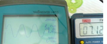
outputs at primary of opt.Xfmr.96vRMS. & 7.1V at secondary on 4 ohms resistor load.The output Xfmr.is 600:4. That is 15W on Pri.12.5W on 4 Ohms some loss on Xfmr.Pic.attached.I couldn't tell what's the THD.I ain't got a distrotion meter
RE:The adj. is very diff.enough to blow the 6080.
RE:6ar11 It's only two 12by7 in one.I do not know it's linear enough.I used this because High Gm and looks good on my amp.also save space.A citation II used 12by7.
Rgds!
Singh
I've made some measurement to the amp.
Input 1.1v at 1kilo Hz.
outputs at primary of opt.Xfmr.96vRMS. & 7.1V at secondary on 4 ohms resistor load.The output Xfmr.is 600:4. That is 15W on Pri.12.5W on 4 Ohms some loss on Xfmr.Pic.attached.I couldn't tell what's the THD.I ain't got a distrotion meter
RE:The adj. is very diff.enough to blow the 6080.
RE:6ar11 It's only two 12by7 in one.I do not know it's linear enough.I used this because High Gm and looks good on my amp.also save space.A citation II used 12by7.
Rgds!
Singh
Attachments
Hi to all,smoking-amp said:With the 6080 cathodes connected to halfway points of the voltage doublers and the plates connected to the full voltage doubler, there is DC current thru the T? xfmrs (unbalanced load on the voltage doublers). The xfmrs are going to get hot.
Biasing of the 6080's appears to be auto-bias by R11 and R18.
This is how I bias the 6080 in my project. Attacted Schematic.
Thanks to all !
Singh
Attachments
Hi,smoking-amp said:The biasing looks fine, but the tube current still appears to be only going thru half of the voltage multiplier still. DC current thru the xfmr will make for a hot running xfmr.
the biasing current is less then 1mA.you saw there are to Xfms in my schmo.but actually is two windings in one, they'll cancell like any pp does.My amp runs with no hot tranformer after hours.It will keep running cool!
Rgds!
Singh
"you saw there are two Xfms in my schmo.but actually is two windings in one, they'll cancell like any pp does"
OH, OK. Wasn't obvious from the schematic.
I would check the capacitance between the windings though if they are on the same xfmr. I prefer to use two xfmrs for Circlotron mode, each with split bobbins, to mimimize common mode capacitance.
OH, OK. Wasn't obvious from the schematic.
I would check the capacitance between the windings though if they are on the same xfmr. I prefer to use two xfmrs for Circlotron mode, each with split bobbins, to mimimize common mode capacitance.
Yeah,It is better to use fullwave rectifier 1 for B+ other for Biasing.It will be no more Simple......smoking-amp said:"you saw there are two Xfms in my schmo.but actually is two windings in one, they'll cancell like any pp does"
OH, OK. Wasn't obvious from the schematic.
I would check the capacitance between the windings though if they are on the same xfmr. I prefer to use two xfmrs for Circlotron mode, each with split bobbins, to mimimize common mode capacitance.
Rgds!
Singh
- Status
- This old topic is closed. If you want to reopen this topic, contact a moderator using the "Report Post" button.
- Home
- Amplifiers
- Tubes / Valves
- simple 6080/6as7 ppp/circlotron project