Miles Prower said:^^
Who uses AM for Part 15 anymore? CW, at the very least, or digital modulation these days.
Even LowFER's use QRSS60 and computers running all night to record the signals.
wrenchone said:Speaking of the 6J6, I've thought of using one in a passive equalization phono preamp using LED bias at the common cathode, figuring that the low dynamic impedance would more or less decouple the stages from each other. Some more bias current for the LED via a separate JFET or ring-of-two current source would lower the LED impedance some more and help out the isolation between stages. I've got a fair number of 6J6s lying about, so I figure I might as well do something with them. This would probably work with the 6X8, too, though I only have a couple of those.
Dude,
JMO, the 6J6 was "born" to be a LTP phase splitter. I don't know if it's quiet enough for mV. level audio work. The upper 30s mu could be problematic too.
You have mail! Reply and a schematic will head your way.
Splitter is not a bad supporting role for what would otherwise be a "plinker".
I'm not convinced that the 6J6 would be a rotter in the phono role. A mu of 38 doesn't disqualify it for me, as I commonly work with a front stage gain of 40X and a back stage gain of 30x for my passively equalized sand state projects. This gets me an overall gain of 40dB, which is very compatible with my system. As always, noise performance will probably vary between manufacturers and individual units. I have a bunch of RCA NOS units, as well as a passel of used tubes of various sorts. The design isn't meant to be the be-all and end-all, just a a stab at using something that would otherwise be auctioned off at my estate sale when I kick it. When I get really serous about doing a phono preamp, I'll probably use some of the 6AM4s and 6HF5s (as well as those 6JK8s) I've been collecting. The 6AM4 looks eccentric enough that I'd want to use it for something. The elements are arranged horizontally, so it looks like a little barrel inside its peanut-sized envelope. Specs aren't too bad, either.
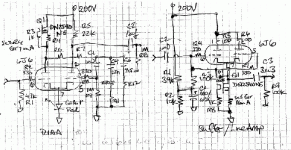
Attached are a couple of back of the envelope schematics for an RIAA preamp and a unity gain buffer/line amp using the 6J6.
For the RIAA stage, the current source loading on the input stage is a kneejerk thing. Cheapskates could probably get away with using a 22k load resistor on that stage, There is enough current going through both tubes so that the bias LED is pushed up into the low impedance region of its characteristic curve, so extra bias current may not be necessary.
I like the MOSFET current sink for the buffer circuit, as I like current source loaded followers. The output cap is sized to operate into a 10k load without a lot of bass sag.
I'm not convinced that the 6J6 would be a rotter in the phono role. A mu of 38 doesn't disqualify it for me, as I commonly work with a front stage gain of 40X and a back stage gain of 30x for my passively equalized sand state projects. This gets me an overall gain of 40dB, which is very compatible with my system. As always, noise performance will probably vary between manufacturers and individual units. I have a bunch of RCA NOS units, as well as a passel of used tubes of various sorts. The design isn't meant to be the be-all and end-all, just a a stab at using something that would otherwise be auctioned off at my estate sale when I kick it. When I get really serous about doing a phono preamp, I'll probably use some of the 6AM4s and 6HF5s (as well as those 6JK8s) I've been collecting. The 6AM4 looks eccentric enough that I'd want to use it for something. The elements are arranged horizontally, so it looks like a little barrel inside its peanut-sized envelope. Specs aren't too bad, either.
Attached are a couple of back of the envelope schematics for an RIAA preamp and a unity gain buffer/line amp using the 6J6.
For the RIAA stage, the current source loading on the input stage is a kneejerk thing. Cheapskates could probably get away with using a 22k load resistor on that stage, There is enough current going through both tubes so that the bias LED is pushed up into the low impedance region of its characteristic curve, so extra bias current may not be necessary.
I like the MOSFET current sink for the buffer circuit, as I like current source loaded followers. The output cap is sized to operate into a 10k load without a lot of bass sag.
Attachments
The only thing I don't like about the differential approach ( it occurred to me the first time I saw the 6J6) is that there's no assurance the two halves of the tube are well-matched, so there could be a lot of picking and choosing. With the approach I've shown I don't have to care about that.
salas said:Doubles nicely. But what about the self noise of such a huge resistor? Won't be amplified by first stage, strongly worsening SNR?
You are correct about caution with those huge grid leak parts. Fortunately, Caddock makes some very quiet parts that meet the need. Mouser stock # 684-MK632V-20M is what I have in mind.
But what about the self noise of such a huge resistor? Won't be amplified by first stage, strongly worsening SNR?
Good for ppm, size and sonic fingerprint, but nV/Hz^0.5 isn't still related to nominal resistance and Johnson?
This is true, but for all the passband frequencies between the 20M resistor and the 47K, the Johnson noise-resistance is the parallel value of the two resistors. i.e.: it is 47K. You might get some large very-low frequency noise, but that could be lost by the output coupling capacitor.
I think this sounds worthy of some building... I have always avoided valve RIAA first-stage, not for the noise, but the avoidance of dc current (+ turn-ON transients) in the cartridge.
The Euro equivalents PCF806 and 30Fxx are very available too.
I'd be tempted to use transistor-cascoding to get the gain high in these..
Assuming grid leak bias with 20 MOhm parts at both 6X8 section control grids, I make a 159 pF. cap. coupling the 47 KOhm cart. load resistor to the pentode as taking care of the 50 Hz. (3180 µS.) pole of the RIAA curve.

 I garbled things pretty thoroughly. RIAA playback EQ is a trio of LOW PASS poles. A 159 pF. coupling cap. between 47 KOhm cart. load and 20 MOhm grid leak resistor is a 50 Hz. high pass pole. NOT GOOD!
Lets start over. A 2122 Hz. (75 µS.) low pass can be achieved by paralleling the 20 MOhm part with 3.75 pF. of capacitance. If the pentode 1st gain block is DC coupled to a ZVN0545A source follower, the same parallel cap. "trick" across the anode load resistor can be used to implement the 500 Hz. (318 µS.) pole. I'm thinking that the high pass "corner" at the pentode's I/P should be about 14 Hz., which seems a reasonable compromise between infrasonic noise rolloff and in band phase shift.
Sufficient net gain from the preamp should not be problematic, even if the triode in the 2nd gain block has a modest mu. Just make the pentode's load resistor "tall" enough.
michaelsamra said:Eli
I wonder what the gain is of the pentode section of the tube?
Mike,
The gm of the pentode is spec'd at 4.6 mA./V. Working into a 27 KOhm load resistor and ZVN0545A source follower, stage gain should easily be 40 dB.
As for noise in the pentode section, we could always try triode connexion and then cascoding with a bipolar transistor. Triode connexion would lose "partition noise" found the pentode mode. In the tests I made on cascodes for my 300B driver circuit, even high-capacitance transistors (BU208 TV sweep part) sounded better than 6SN7s in the upper cascode position.
perhaps a bigger problem with cascodes or pentodes in RIAA modules is the increase in sensitivity to power supply noise.
The GE data sheet for the 6X8 does show characterisation for operating both sections at 50V, and maybe that could be a good solution - minimize noise by operating at high current, low voltage and run the whole thing off lead-acid batteries. A quick look at my favourite disti shows 10x 12V/2,2Ah are only £54 now (USD80, Euro60) - so why not? 120V at low impedance, no hum, no chokes, no induced fields, no reason for power supply noise. With the series-string 300mA versions of the common-cathode valves, you could run the heaters and 4 x 10mA anodes currents for 6+ hours betweeen charges.
http://www.rapidonline.com/Electric...12V-Sealed-lead-acid-monobloc-batteries/73355
perhaps a bigger problem with cascodes or pentodes in RIAA modules is the increase in sensitivity to power supply noise.
Rod,
It's a given that the PSU will be well filtered and regulated. If you look over on AA, you'll find remarks about batteries being noisy.
Grid leak bias rates to yield less than 2 V. of potential differential between grid and cathode. I'm considering a 75 V. 0C2 for g2 B+, given that bias limitation.
GE specs for 6X8
The GE specs describe the 6X8 as the equivalent of one 6j6 triode and a 6ag5 pentode. The 6ag5 specs show triode curves.
I am only a beginner, but the curves for both the 6j6 and 6ag5 triode strapped look pretty respectable. They both have a mu in the low 40s.
I made a preamp using the two triode sections of the 6X8s (and ignoring the pentode). It sounds quite good. Next I will try to make a preamp out of the two 6ag5s triode strapped. Given the common cathode, the solution seems to be use just one of the two sections of the tube.
I can't take it any further because I don't know how to use an oscilloscope, but I think that the tube is definitely not a plinker.
Al link to the GE specs is on the Duncanamps.com site here
TDSL Tube data [6X8]
The oldradio link is the one you want.
- Status
- This old topic is closed. If you want to reopen this topic, contact a moderator using the "Report Post" button.
- Home
- Amplifiers
- Tubes / Valves
- 6X8 Pentode/Triode Musings