My gut says you will want some feedback. It also says that the regulator can be built off of the B+ supply saving you a transformer. Also, I think the supply is cleaner than necessary, and the last RC filter can likely be dropped (and the draw from the regulator may be enough to drop any extra volts you may have). Mind you, this is all without looking at the datasheets, so I may be totally wrong. ")
I would think the one transformer would do - the 2A5s can run from the 6.3V winding with a 1 Ohm (or so) dropping resistor. I agree you may want feedback - the 6SL7 has enough gain for that. If you go without feedback,the 6SN7 has enough gain.
The cap across the VR tubes shouldn't be more than .047 uF, according to the data sheets. You can use something larger IF you add a resistor in series (forget the value...).
The cap across the VR tubes shouldn't be more than .047 uF, according to the data sheets. You can use something larger IF you add a resistor in series (forget the value...).
Proper pentode operation requires that g2 be at the same AC potential as the cathode. A cap. is needed.
I agree with other posters about some NFB being in order. You really need to do something about an inadequate damping factor. The so called plate to plate connection might work out very well. Of course, the "classic" global connection from O/P trafo secondary to voltage gain cathode is also available.
I agree with other posters about some NFB being in order. You really need to do something about an inadequate damping factor. The so called plate to plate connection might work out very well. Of course, the "classic" global connection from O/P trafo secondary to voltage gain cathode is also available.
dsavitsk said:My gut says you will want some feedback. It also says that the regulator can be built off of the B+ supply saving you a transformer. Also, I think the supply is cleaner than necessary, and the last RC filter can likely be dropped (and the draw from the regulator may be enough to drop any extra volts you may have). Mind you, this is all without looking at the datasheets, so I may be totally wrong.
I might add FB from OPT to the Cathode of the SL7 once I get up and running.
(how can a PS ever be "CLEANER THAN NECESSARY"?)
The 2A5's filaments draw 1.75A so I NEED the extra tranny no matter what because the 6 volt winding on my tranny is barely 2 amps and I would rather not "push" it.
disco said:I guess you don't need the high amplification of the SL7. Exchange it for a SN7 which has lower Ri so the bandwith will be higher.
Unfortunately my experience with the source I have (A PC sound card) requires a bit more gain than the SN7 (I actually prefer to use 6FQ7/6CG7) can give. In addition I might want to up the B+ in the future and I will need the gain to drive the tubes with more bias.
Eli Duttman said:Proper pentode operation requires that g2 be at the same AC potential as the cathode. A cap. is needed.
Eli,
Can you explain this Cap?
Thanks,
REVISIONS NEED HELP! NFB
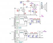
Well after careful consideration of everyones suggestions I am encorporating them into a revision.
By switching out to a 6V heated Rectifier I "freed up" the 5V winding for the 2A6's (DUH why didn't I think of that the first time?)
I am pretty sure the schematic should function as it stands now just need a little help calculating a possible starting point for the NFB. I will probably place a switch and some "breadboard" off chassis to allow me to switch in and out some different amounts and with different capacitors. Can anyone help me out with a starting point. (First timer at NFB)
Attachments
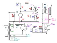
coldcathode said:I have never designed a pentode amp before.
I tried my hand at it with VR screen regulation. Most if not all the components are "junkbox" stuff. I happened to have (4) 2A5's.
Any comments? Suggestions?
I would save them for other applications. A triode-strapped 2A5 (42, 6F6G/GT) is one the nicest indirectly heated devices you can get for interstage transformer coupling.
It is more linear than most triode-strapped beam power tubes and many indirect heated triodes! ... probably because of its full cylindrical geometry.....
With 4 tubes you could also go for a "mini-Olson" amp: triode strapped at 350V/25mA with 10K plate-to-plate for 3W at 1% THD (it is full Class A...) and 4W max output.
45
45,
Thanks for the suggestion BUT, as the title of the posting implies I am building from my "junkbox" of parts. I have only TWO STRONG 2A5's (the other two are pretty weak) and the only OPT's I have are about 4100K-8. My original thought was to go SET BUT I can't even get 1 watt that way. (If my speakers were a little bit more sensitive I would consider it but they are only 88dB)
I am figuring about 4W as I drew it?
I did notice the triode curves look real nice just down on power.
Are you suggesting that maybe I should take this project off the table and save the 2A5's for a Pure Class A PP Triode? Will I be that pleased with the results?
As far as Interstage Trannys I would rather stay away from them. My reason is mostly cost. I am new(ish) to tubes and keeping the budget down is important. (the "WAR DEPT" or "Wife" doesn't allow too much in the way of purhcases since I am out of work right now)
Since this is more of a "learning" excercise maybe if I could get some "validation" that this would have worked had I actually built it I could move on to something else?
How about this?
I have over a dozen NOS 1625's (807's with 12V heaters and different base) maybe I should just adapt this schematic to those tubes? Most likely get more power and same learning experience?
One more ?? 45.
I have had difficulty in finding REAL information on the 2A5 mostly referencing 42 and 6F6. In plowing thru the info there is always a reference to issues with resistance coupling of the drivers. I cannot however find what those issues are? Since you mentioned using interstage coupling I guess you have that answer? Could you fill me in or steer me to where I can find it?
coldcathode said:45,
Thanks for the suggestion BUT, as the title of the posting implies I am building from my "junkbox" of parts. I have only TWO STRONG 2A5's (the other two are pretty weak) and the only OPT's I have are about 4100K-8. My original thought was to go SET BUT I can't even get 1 watt that way. (If my speakers were a little bit more sensitive I would consider it but they are only 88dB)
Yes triode-connected SE is definitely not enough.
coldcathode said:I did notice the triode curves look real nice just down on power.
Are you suggesting that maybe I should take this project off the table and save the 2A5's for a Pure Class A PP Triode? Will I be that pleased with the results?
This is the original Olson amplifier:
http://www.bonavolta.ch/hobby/en/audio/6f6.htm
It used 4x6F6 for each channel for 5W at a typical 0.7% THD! The max output was close to 8W.
I re-built it for friend of mine with some mods and it is really really nice.
I "removed" anything before the 50K pot (after the first valve), for V2 I used 1/2 6SL7 for each channel in place of the 6SN7. Cathodyne splitter (1/2 6SN7 for each channel) and output stage identical to the original.
I used a SS rectifier with choke filtering.
coldcathode said:How about this?
I have over a dozen NOS 1625's (807's with 12V heaters and different base) maybe I should just adapt this schematic to those tubes? Most likely get more power and same learning experience?
I don't know the 1625's. Among the 1600-series the most similar to 2A5/6F6G is the 1621.
The 2A5 is identical to 6F6 and 42 except for filament ratings.coldcathode said:One more ?? 45.
I have had difficulty in finding REAL information on the 2A5 mostly referencing 42 and 6F6....
This is very clear here: http://frank.pocnet.net/sheets/127/6/6F6.pdf
Also you find grid resistance limitations: 0.5 Megohm for self-bias and 100K for fixed bias.
45
Very good 6F6G's are the Russian 6F6S:
http://frank.pocnet.net/sheets/113/6/6F6S.pdf
You can find NOS quads for 20-25$ on ebay.
45
P.S. About interstage transformer coupling, I meant using the 2A5 as a driver for bigger tubes.
http://frank.pocnet.net/sheets/113/6/6F6S.pdf
You can find NOS quads for 20-25$ on ebay.
45
P.S. About interstage transformer coupling, I meant using the 2A5 as a driver for bigger tubes.
I have over a dozen NOS 1625's (807's with 12V heaters and different base) maybe I should just adapt this schematic to those tubes? Most likely get more power and same learning experience?.......I don't know the 1625's.
The 1625 is a 6L6GA or GB with a 12 volt heater in an odball base. Use them in your schematic with a 620 ohm cathode resistor. Triode wired, it should provide 2 or 3 watts, 5 to 8 in pentode with some feedback to lower the output impedance. Of course you will need a 12 volt filament supply. You might get by with the 6 volt and the 5 volt windings in series. You can still run the 6 volt tubes off of the 6 volt winding and the 12 volt tubes off of both windings in series. Total draw off of the 6 volt winding is 1.2 + .3 + .45 + .45 = 2.4 amps
If you can find sockets and plate caps, and your power transformer can live with 2.4 amps off of the 6 volt winding, I would try it. This is the "minimal expenditure for new parts" mode that I am also in. I just happen to have a much bigger collection in my "junk box". You have 2 to 4 good 2A5's, you have more than 12 1625's, which do you want to learn on. Which would you feel the best about accidentally blowing up?
Thanks Tubelab,
I think I will actually Triode Strap the 1625's for SET.
I was pretty sure they were actually 807's with the different pinout and heater. A few manuals have referenced them as being the same internal structure.
I know, I know the 6L6 family tree has a lot of branches!
You are absolutely correct there is some very expensive smoke inside those 2A5's!!
I will play with an 807 Triode Curve and come up with some OP's and a schematic and post my ideas.
Thanks again to all. I will also develop the Parallel Push Pull ALL ST schemactic over the next few days. Any suggestions? I have a few directly heated triodes in my collection.
BTW Tube Lab, I have some Chinese ("Ceramic") Plate caps for the tubes, only trouble is they don't fit too well , (sorta like your 9 pin socket post yesterday) I end up having to fiddle with some copper foil to get them to make good contact.
I was pretty sure they were actually 807's with the different pinout and heater.
They are. The 807, the 1625, and the 6BG6 were all made from the 6L6GA or 6L6GB depending on when they were made, and who made them. I had a bunch of all 3 tubes and some vintage 6L6 types. Due to poor handling before I got them many were broken. I took a lot of them apart and verified that the internal construction of like brands and vintages are indeed identical. In a move to lower my storage costs I sold off the tubes that I didn't think I was going to use in the next few years including all of these. At one time I had over 100,000 tubes. My warehouse costs were $5K per year.
I did crank up some NOS WWII vintage 807's before I sold the lot. They sound pretty good. They can be used to make some really killer P-P amps. The 6L6 family has a limited plate voltage capability because the plate pin (3) it adjacent to the filament (2). They have been known to arc over in extreme situations like a guitar amp cranked to 11. The 807 does not have this limitation.
They are NOT the same as the later 6L6GC's and can not be subjected to the type of abuse that I routinely feed the Chinese 6L6GC's. Plate dissipation limit is 19 watts and the plate voltage should be limited to about 360 volts in triode mode due to the screen grid rating. This is the plate to cathode voltage. The B+ can be around 400 volts due to the cathode voltage, and the drop across your OPT.
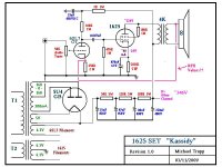
Well, the "Junkbox 2A5" amp is now a "JunkBox 1625 SET"!
Codenamed "Kassidy" after my youngest daughter who happens to be named (albeit different spelling) after my favorite Grateful Dead song.
A little help on the NFB network would be appreciated.
Gain of the 6SL7 is about 40V+ I need most of that because I have a very low voltage signal from my PC sound card. <1V
Can someone give me a starting point? Tubelab?
Attachments
If you are going to use traditional GNFB you need to ground one side of the OPT secondary, and insert a resistor in series with the red wire. I usually get everything working without feedback, then insert a 100 K pot and turn it until I get results that I like. If the gain goes up or the amp oscillates when feedback is applied, reverse the secondary wires on the OPT.
I find that a 6L6 type tube in triode may sound best with no feedback at all. Another possibility is to dispense with the traditional GNFB and use local feedback on the output stage. This is not hard. Use a resistor from the plate of the 1625 to the plate of the 6SL7. Value will be rather high maybe 330K. Again experimentation is needed.
I find that a 6L6 type tube in triode may sound best with no feedback at all. Another possibility is to dispense with the traditional GNFB and use local feedback on the output stage. This is not hard. Use a resistor from the plate of the 1625 to the plate of the 6SL7. Value will be rather high maybe 330K. Again experimentation is needed.
- Status
- This old topic is closed. If you want to reopen this topic, contact a moderator using the "Report Post" button.
- Home
- Amplifiers
- Tubes / Valves
- "Junkbox" 2A5 SE