Hey all,
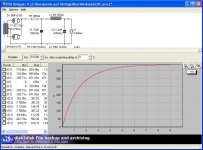
I have a Dual Mono tubeamp. Each power supply has a 450 - 0 - 450 tranny going to a pair of 5R4-GYB. It then to a RCLC filter (680 ohm, two series 150u/450V electroylitics (for 75u/900V), 2H 100ohm max, 1200u/450V). Final output voltage was around 350VDC. Current out is around 150ma.
I really hated that setup as those 680 resistors were so damn hot.
At 150ma, the resistors were drawing around 15 watts, and the Dale resistor was rated at 50 watts, but it just was getting everything in the chassis so hot...
Attached is the PSU modeled on PSU Designer as I have it. It gives me a little warning that I am exceeding .71A IFRM at .75A. I am planning on putting a current limiter on the primary to fix this issue...
The Choke is a Thordarson TF5SX04ZZ and it looks to be 2H, 100 ohm max 2000V test.
Bleeder resistor on 1200u cap is 20K ( I think)
Attachments
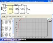
What I want to do is go with a LCRC filter to get rid of that 680R resistor (I have read that LC filtering is better than RC filtering anyway).... I planned on the 1 ohm resistor between the 75u and 1200u as I have it handy and wouldn't be exceeding any wattage issues at 150ma...
Attached is the power supply that I want to do...I put the 1u PP cap in front of the Choke, as I have read that it has some benefits...I can just as easily take it out, with a little change to output voltage...
Any issues of this setup?
I still have the IFRM warning that shows it is exceeding the .71V with 1.3A...again the current limiter should fix this...
The current limiter I have is a CL130 - it is rated for 1.6A and 50 ohm, so on the mains it should reduce current to both trannies primaries during startup...
Attachments
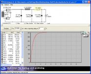
Choke input would be perfect but 2Hy is marginal - you might try it anyway. Just delete the resistor and input capacitor. If supply ripple ends up too high, an additional R-C section (R can be quite small) will do it. Say L-150 uF-100R-1200uF.
<edit> 5.5 Ohm secondary? That must be a killer transformer! An input cap of 1 uF or less is a good thing - it limits the peak voltage on transients.
<edit> 5.5 Ohm secondary? That must be a killer transformer! An input cap of 1 uF or less is a good thing - it limits the peak voltage on transients.
The easy way out of the heat issue is to convert the PS topology to a choke input filter. Will sound far better and bring the voltage out of the initial filter to around 450 x 0.9 = 400 with no heat, less whatever you lose in the tube recifiers.
If the final required voltage is 350, then the headroom you have is just about perfect for one of our current sourced shunt regulators we name the "SuperReg" which will again greatly improve your sound. URL is:
http://www.vacuumstate.com/index.tpl?rubrik=24&lang=2&a=%98C%7F%83G%9EI%5E&b=733839.6341925161
Regards, Allen (vacuum State)
Just delete the resistor and input capacitor. If supply ripple ends up too high, an additional R-C section (R can be quite small) will do it. Say L-150 uF-100R-1200uF.
Are you referring to the first PSU or second?
So get rid of the 1u polyproylene?
I can do L-75u-100R-1200u
Is the source impedance of that transformer correct? It seems mighty low...
Having a little trouble reading it, but it looks to say 100ohm max. I have not found much info on the choke...Thordarson TF5SX04ZZ..
Is 20K bleeder across the 1200uf OK?
Is there an issue around min current for Lcrit?
john65b said:
<snip>
I still have the IFRM warning that shows it is exceeding the .71V with 1.3A...again the current limiter should fix this...
The current limiter I have is a CL130 - it is rated for 1.6A and 50 ohm, so on the mains it should reduce current to both trannies primaries during startup...
The current limiter will not fix this issue as IFRM is the peak current drawn whilst the rectifier is conducting, and the current limiter's resistance when hot is rather small. Higher secondary winding resistance or a redesign to limit the pk current will. As SY indicated the DCR listed for that transformer is rather low - try measuring the winding resistance of your transformer and edit the model in your simulation to use that. I bet it is probably a couple of hundred ohms.
Note that choke inputs have a propensity to buzz if the wrong choke is used, and I have a number of friends who now after a number of years of use are experiencing choke failures due to insulation breakdown issues, and winding shorts due to vibration. You will need to add a snubber at the choke input (or across the choke in some cases) in order to control the choke emf when the rectifier is not conducting. In some cases a small input capacitor eases that issue, but these are primarily used for fine tuning the output voltage under load. Make sure that the choke is sized appropriately for the load current and has sufficient inductance to regulate properly over the expected operating current range - also be aware that until the output stage is drawing current the output voltage will be very close to what you would get with a cap input filter and make sure that all components can handle this voltage level safely.
In your sim, you show the source impedance at 2.275R. That's going to throw off the entire calculation once you lose the 680R. Measure that, then put in the right value and sim with an LC filter.
edit: I see Kevin and I crossposted. Running a quick sim, you need more L, less C.
edit: I see Kevin and I crossposted. Running a quick sim, you need more L, less C.

I have been thinking of a Tube/SS rectifier hybrid as attached. I cannot sim it in PSU-Designer, but it should equate to a SS rectifier, with tube softstart...I have seen a few similar to this ad should be OK...
Anyway, any comments?
Anyway, any comments?
An externally hosted image should be here but it was not working when we last tested it.
john65b said:I have been thinking of a Tube/SS rectifier hybrid as attached. I cannot sim it in PSU-Designer, but it should equate to a SS rectifier, with tube softstart...I have seen a few similar to this ad should be OK...
Anyway, any comments?
There is no benefit I can see to wiring a solid state diode and a hollow state diode in series. The VT diodes will have the same "soft start" characteristic regardless. Some designers might go ahead and include a hollow state diode after the ripple filter, or, sometimes ahead of it. Either way, the hollow state diode operates as an always on DC gate. What you've got there isn't the same.
Or may be you're thinking of a hybrid +/- supply?
- Status
- This old topic is closed. If you want to reopen this topic, contact a moderator using the "Report Post" button.
- Home
- Amplifiers
- Tubes / Valves
- Tubeamp power supply - LC question