In another thread, theoldtrout said: Arthur Radford used this idea to drive a pair of EL34’s in his very successful STA15 and STA25 amplifiers. I’m about to experiment with this myself using a CCS in the tail - could be interesting.
I used to think the Radford splitter was an odd-ball idea. However, inspired by the above post, I tried an LTspice model using:
* 1/2 6SL7 with CCS load;
* 6AU6-6SL7 LTP splitter with cascode BJT CCS in the tail;
* 6SN7 cf drivers;
*EL34 pentode-mode PP outputs, into 3.5k p-p load;
* Global NFB (with the usual compensation to prevent LF and HF instability).
It models very well, showing good balance and low distortion - much lower than I can get with the usual Mullard-type circuit using a conventional double triode splittter or with a dual pentode splitter.
I realize it's only a model, but . . .
Hi Ray_Moth,
there is an article from Mr. A.R. Bailey himself about this interesting Schmitt type inverter: A New Phase-Splitter, A.-R. Bailey, Wireless World, September 1962. Probably Mr. Bailey designed this circuit for Radford and/or even worked for them for some time.
Also, there is a French language article summarizing it: Un Inverseur de Phase Amélioré, Revue du Son. Both articles definitely can be found as scans somewhere on the ´Net.
Some time ago I wrote some sort of analysis of those typical Radford PP amp frontend/splitter-combos from Mr. Bailey myself, which can be found here at Jogis Röhrenbude (German language).
The full "beauty" of this circuit is only revealed in the amp context, working together w/ the input stage in front of it and power stage after it. Just picking this dissimilar tube section Schmitt inverter out of its context doesn´t make much sense, I think, because when viewed as a "standalone splitter module" alone, it isn´t much appealing ...
Regards,
Tom Schlangen
EDIT: P.S.: You wanting to improve it by putting a CCS in the fully intentional very short "long tail" (actually, this is not an LTP whatsoever), clearly shows you didn´t understand how it really works")
there is an article from Mr. A.R. Bailey himself about this interesting Schmitt type inverter: A New Phase-Splitter, A.-R. Bailey, Wireless World, September 1962. Probably Mr. Bailey designed this circuit for Radford and/or even worked for them for some time.
Also, there is a French language article summarizing it: Un Inverseur de Phase Amélioré, Revue du Son. Both articles definitely can be found as scans somewhere on the ´Net.
Some time ago I wrote some sort of analysis of those typical Radford PP amp frontend/splitter-combos from Mr. Bailey myself, which can be found here at Jogis Röhrenbude (German language).
The full "beauty" of this circuit is only revealed in the amp context, working together w/ the input stage in front of it and power stage after it. Just picking this dissimilar tube section Schmitt inverter out of its context doesn´t make much sense, I think, because when viewed as a "standalone splitter module" alone, it isn´t much appealing ...
Regards,
Tom Schlangen
EDIT: P.S.: You wanting to improve it by putting a CCS in the fully intentional very short "long tail" (actually, this is not an LTP whatsoever), clearly shows you didn´t understand how it really works
Looks completely familiar to me. Its cathode coupled anti-triode.
Tail wagging the dog. By that, I mean driving from the Anti-side.
Whichever device has the overwhelmingly Higher Gm becomes
the Anti-complement of the weaker Gm device. A transparent
flavorless inverter of the weaker device's single endedness.
Or you can look at it as a cascode, bent into a U shape.
CCS tail not strictly necessary, but it won't hurt anything.
Hi kenpeter,
Of course it would hurt, but admittedly this is one of the finer details of the circuit.
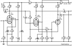
Hint: Have a close look at the ECF82 pentode screen grid feed and its AC clamping, then think about what changing smallish R13 (see below) to a CCS will do:
- to the stage gain of the ECF82 pentode section
- to the distortion of the ECF82 pentode section
- to the output impedance of the ECF82 pentode section
Think local cathode FB for the pentode section - we don´t want to lose its merits, eh
Redrawn circuit for convenience see below .
Regards,
Tom Schlangen
EDIT: Uh, oh, the linked circuit picture suddenly got replaced by a "deeplink" sign. I attached it as a file again below. Hey moderators, I have drawn this schematic myself!
CCS tail not strictly necessary, but it won't hurt anything.
Of course it would hurt, but admittedly this is one of the finer details of the circuit.
Hint: Have a close look at the ECF82 pentode screen grid feed and its AC clamping, then think about what changing smallish R13 (see below) to a CCS will do:
- to the stage gain of the ECF82 pentode section
- to the distortion of the ECF82 pentode section
- to the output impedance of the ECF82 pentode section
Think local cathode FB for the pentode section - we don´t want to lose its merits, eh
Redrawn circuit for convenience see below .
Regards,
Tom Schlangen
EDIT: Uh, oh, the linked circuit picture suddenly got replaced by a "deeplink" sign. I attached it as a file again below. Hey moderators, I have drawn this schematic myself!
Attachments
I agree that technically it is not a true LTP and I thank you for your post; it has certainly made me re-think if it is worth tampering with the cathode circuit by using a CCS. I note that the later Radford STA25’s [made by John Widgery] used the same phase-splitter but had the anode resistors connected to a potentiometer with the wiper connected to HT to adjust balance. Also the pentode screen voltage was clamped by a zener diode.
CCS works. R14 and R9 merely have to be the same value.
As with a Cathodyne, even if drive signals are identical and
opposite into exactly equal loads. The plate impedances are
not equal and won't react similarly if the loads misbehave.
Unless there is something in the Radford that fixes this,
and I'm missing it.
--------------------------------------------
You don't "need" resistive feedback under the Pentode
for the Pentode to be linear. You have Triode feedback.
You merely need it to be a strong follower of the input.
Mu of Triode V2A and R14 will decide the current that
reflects back through the Pentode into R9.
And assuming both plate resistors driving identical loads,
it works at least as good as a Cathodyne. But with gain.
Matters not the small detail of V2B screen bypassed to
ground rather than cathode. As the functions of V2B
as strong cathode follower and top half of a U bent
Casocode, are not where the current control happens.
With CCS in the tail, That decision is for V2A and R14.
--------------------------------------------
It might help to understand why Radford favored a
small resistor tail, if we had a full translation? All I
got to go on for now, is your schematic.
I think the reason R13 is at 8.2K here, is for a not so common mode feedback loop back to the EF86 plate thru R6. Everything is DC coupled between these tubes. The ECF82 triode has a higher gm than the pentode, so AC signal causes net current variation to develop an AC voltage across R15, which feeds back to V1 via R6. A CCS would spoil this DC biasing feedback loop.
If it weren't for this DC loop, I would put a CCS in. More linear.
For possible improvements, I would try a small Mosfet of Depl. FET (LND150) to operate the ECF82 screen grid. Source to screen, gate to Vref, and drain to the pentode's plate. That way th e screen current gets put back into the plate output as if purely triode.
Don
For possible improvements, I would try a small Mosfet of Depl. FET (LND150) to operate the ECF82 screen grid. Source to screen, gate to Vref, and drain to the pentode's plate. That way the screen current gets put back into the plate output as if purely triode. (This only works if the dynamic plate voltage stays above the screen voltage though.)
If the triode has the higher Gm, thats a whole different animal.
It becomes an anti-pentode and the "top half" of the U, and
Mu won't apply in a Gm limited (to that of the weaker pentode)
situation. I guess current control must come from somewhere
else than the Triode for this to work.
I'm not buying any loop feedbak thru R6 to the EF86 plate.
As you are ignoring the bypass effect of C3.
C3:
It's a DC bias servo loop for the ECF82, C3 is OK.
The triode section of the ECF82 is still providing plate Mu feedback to the splitter here, a dual pentode splitter would be operating open loop. So looks like the pentode side gets rid of Mr. Miller, and the triode side keeps things linear.
Don
It's a DC bias servo loop for the ECF82, C3 is OK.
The triode section of the ECF82 is still providing plate Mu feedback to the splitter here, a dual pentode splitter would be operating open loop. So looks like the pentode side gets rid of Mr. Miller, and the triode side keeps things linear.
Don
With a CCS, wouldn't you want to attach the screen's AC bypass to the cathode instead of ground?
Yes, SY, that's what I did in my model. I found 0.082uF did the job, one of the variables I twiddled with in trying to smooth out the LF response. (I didn't bother to try bypassing the screen to ground because it didn't seem to make sense.)
The other variables that affect LF stability are the cap in the step-network on input to the splitter and, of course, the caps from the splitter to the cf driver stage.
You wanting to improve it by putting a CCS in the fully intentional very short "long tail" (actually, this is not an LTP whatsoever), clearly shows you didn´t understand how it really works
Ya got me, Tom, I admit I don't understand how it really works. More to the point, I dom't understand why it works, but it certainly seems to. I went for a high-mu triode but I could have gone for one with high Gm like a 6DJ8 - although with a 6DJ8 the plate-cathode voltage would have to be treated with caution.
If you are using a low Gm triode, it works for the very reason
I have already explained. The triode's Mu is the most current
limiting factor, therefore the entire U-bend cascode is linear.
The Pentode isn't in control of anything, except both cathode
voltages. As a cathode follower, and top half of a cascode.
But Smoking has asserted that the Triode in Tom's schematic
of the Radford has the higher Gm. If that is the true case, my
theory falls apart (or at least isn't linear anymore). I do not
yet fully understand how the original design actually worked
with a Pentode in control of current, and remained linear???
I'm assuming Tom will offer a translated explanation sooner
or later.
I suppose the ground referenced screen could be seen acting like a hidden UL feedback, and so effectively linearizing the pentode side some. Putting the bypass to cathode would null that effect out.
So, I would go with the LND150 trick to put the screen current back into the plate circuit (so CCS'able then), and leave the screen referenced to ground (Vref for the LND150 gate ground referenced. This only works for cases with the min. plate voltage staying above the screen voltage.).
Don
So, I would go with the LND150 trick to put the screen current back into the plate circuit (so CCS'able then), and leave the screen referenced to ground (Vref for the LND150 gate ground referenced. This only works for cases with the min. plate voltage staying above the screen voltage.).
Don
"What was I thinking???...."
Translation (I think):
The triode's plate voltage reflects back to it's cathode via inverse Mu effect (4th circuit topology thingie, grid grounded). That connects to the pentode's cathode, affecting the pentode grid to cathode voltage. So the triode is still controlling. Also, the pent. screen UL effect is coming in as 1/Mu(p) there too, to linearize a little more.
Don
No, it works even if the Pentode holds the cathode voltage
constant. A change in Triode plate voltage will be reflected
in the Pentode's plate voltage. Assuming equal loads, and
a pentode that is willing to conduct enough to keep up.
I'm just saying that Mu and the Triode's plate resistor may
be restricting Triode current far more than the Triode's Gm.
If that brings the current change within the grasp of the
Pentode to conduct the opposite, the problem is solved.
Well, in any case, I think the hidden screen UL, and the triode's inverse Mu, keep this thing humming linearly. But the whole scheme seems to be just for the purpose of getting the Miller effect down on the input (pent.) grid.
So why not just use two identical triodes with a cross neutralization cap from the 2nd plate back to the input grid, so much simpler. Maybe put both neut. caps in for complete symmetry.
Another useful mod. would be putting in a center tapped inductor for the two plate loads (for either scheme). Guaranteed 180 degree splitting and twice the output voltage swing. Good for screen drive amps.
Looks like a Nachbaur cathode coupled paraphase. A good way, perhaps, to get rid of some of those oddball 6X8s (pentode/triode with cathodes internally connected). This would have the same problem as any other paraphase: unbalanced harmonics between phases.
Why these folks persist in doing stuff like this escapes me completely: Van Scyoc's, Isodynes, and now this -- all more complex than either a cathodyne or an LTP, and they don't work as well. The paraphase is a quick 'n' dirty solution, but still, more complex than a good old cathodyne. Somebody's got too much time on their hands.
Why these folks persist in doing stuff like this escapes me completely: Van Scyoc's, Isodynes, and now this -- all more complex than either a cathodyne or an LTP, and they don't work as well. The paraphase is a quick 'n' dirty solution, but still, more complex than a good old cathodyne. Somebody's got too much time on their hands.
- Status
- This old topic is closed. If you want to reopen this topic, contact a moderator using the "Report Post" button.
- Home
- Amplifiers
- Tubes / Valves
- Radford pentode-triode LTP splitter