Fiat Flux.
Hi,
A lot of the problems experiencied with PTs can be avoided by the very design of them.
The use of electrostatic shielding helps no doubt as do copper bands around the core.
Anyone remember the Fluxdumpers once offered by Hifi-News' Accesories Club?
Audiofanatic,
Ironically, I first saw the idea published in the now defunct Dutch magazine Audio&Techniek.
For good measure try using Schottky diodes (if you can find them at the appropiate PIV) or/and use snubbers across them.
Limited BW PTs can be a blessing which is why I stay away from toroids.
Indeed, use steel chassis as a RFI shield and use a copper groundplane underneath for signal ground.
Clever trick, EC8010.")
Cheers,
Hi,
A lot of the problems experiencied with PTs can be avoided by the very design of them.
The use of electrostatic shielding helps no doubt as do copper bands around the core.
Anyone remember the Fluxdumpers once offered by Hifi-News' Accesories Club?
Audiofanatic,
How it's clear to me and I'll try it out on my next project my 300B and my SE EL34!
Ironically, I first saw the idea published in the now defunct Dutch magazine Audio&Techniek.
For good measure try using Schottky diodes (if you can find them at the appropiate PIV) or/and use snubbers across them.
Limited BW PTs can be a blessing which is why I stay away from toroids.
The spacers are effectively a magnetic resistance, and prevent flux from entering the steel chassis.
Indeed, use steel chassis as a RFI shield and use a copper groundplane underneath for signal ground.
Clever trick, EC8010.
Cheers,
My experience with HT Schottkys has not been good. I have successfully used them in really low-current circuitry (microphone power supply), but a more powerful application exploded. When I replaced them with STTA512, everything worked perfectly...
I posted a photo on another thread of the Schottky result:
http://www.diyaudio.com/forums/showthread.php?s=&postid=156721#post156721
Yes, power transformers actually benefit from poor bandwidth!
I posted a photo on another thread of the Schottky result:
http://www.diyaudio.com/forums/showthread.php?s=&postid=156721#post156721
Yes, power transformers actually benefit from poor bandwidth!
how important is this REALLY?
I've been thinking a little bit and wonder if people have experience saying that orientation of tubes with respect to transformer magnetic fields is important. If so, what is the problem we're trying to solve?
The reason I ask is that I can imagine that in most cases one could easily screen out the magnetic field with little difficulty. For many output tubes, the plate structure completely surrounds the grid(s) and cathode, so I would imagine that the plate would effective act as a shield blocking any magnetic fields.
I'm not sure if preamp tubes have this self-shielding behavior, but one can always add tube shields and then one doesn't need to worry about those either.
Finally, if the magnetic field does penetrate the space between anode and cathode, how big an effect is it? Won't it just slightly curve the path of the electrons and slightly shift the I-V curves?
So Frank or other experts, please educate me. Is this a real issue or are we just obsessing over secondary effects.
----Gary
Schottky Deadky.
Hi,
The newer SiCa types are only just now hitting the market...slowly.
One way to make'm a bit stronger is to // them.
I'll need to look these up.
On a general note I find tube circuits to be far less sensitive to diode crud than their sand brethren.
Any thoughts?
Cheers,
Hi,
My experience with HT Schottkys has not been good.
The newer SiCa types are only just now hitting the market...slowly.
One way to make'm a bit stronger is to // them.
When I replaced them with STTA512, everything worked perfectly...
I'll need to look these up.
On a general note I find tube circuits to be far less sensitive to diode crud than their sand brethren.
Any thoughts?
Cheers,
Re: Schottky Deadky.
Oh, I don't know about that, Frank. The bits came out very fast, and I am told that I had a white face.
Yes, valves are so much more tolerant. If you short-circuit a valve rectifier, you get sparks, and possible damage to the rectifier. Do the same with silicon, and there is an almighty bang, and the silicon is generally destroyed. Sadly, valve rectifiers are perfectly capable of generating noise. It's definitely worth avoiding powering heaters from the same transformer that provides the HT and heater supply to the rectifier.
fdegrove said:The newer SiCa types are only just now hitting the market...slowly.
Oh, I don't know about that, Frank. The bits came out very fast, and I am told that I had a white face.
Yes, valves are so much more tolerant. If you short-circuit a valve rectifier, you get sparks, and possible damage to the rectifier. Do the same with silicon, and there is an almighty bang, and the silicon is generally destroyed. Sadly, valve rectifiers are perfectly capable of generating noise. It's definitely worth avoiding powering heaters from the same transformer that provides the HT and heater supply to the rectifier.
THE SIZE OF IT.
Hi,
Well, you do have a point...maybe we're just obsessed.
In a nice way I'd hope...
Anyways, did you ever experience tubes that were going in all directions, even to the point of self-destruction by the mere fact that you were coming close with your hand?
Tubes that were impossible to bias?
Infamous examples are some 6550s, 8417s etc.
Maybe we're pushing it, than again I always feel that when something's worth doing it's worth doing right, right?
Another way of looking at things is when you need to design stages that need to handle milivolts or tenths of milivolts, by doing so you'll soon notice that every single detail has an impact on the endresult....sure got me paranoid in the end.
Murphy told me never to count on chance to fix things for me so I wouldn't count on the shielding action of an anode to do this, it's pot luck if it does IMO.
Cheers,
Hi,
Is this a real issue or are we just obsessing over secondary effects.
Well, you do have a point...maybe we're just obsessed.
In a nice way I'd hope...
Anyways, did you ever experience tubes that were going in all directions, even to the point of self-destruction by the mere fact that you were coming close with your hand?
Tubes that were impossible to bias?
Infamous examples are some 6550s, 8417s etc.
Maybe we're pushing it, than again I always feel that when something's worth doing it's worth doing right, right?
Another way of looking at things is when you need to design stages that need to handle milivolts or tenths of milivolts, by doing so you'll soon notice that every single detail has an impact on the endresult....sure got me paranoid in the end.
Murphy told me never to count on chance to fix things for me so I wouldn't count on the shielding action of an anode to do this, it's pot luck if it does IMO.
Cheers,
Self-screening?
As you point out, the anode is generally made of nickel (which is magnetic), and it encloses the grids. However, although electrostatic fields can be stopped by any thickness of conductor, a magnetic screen works by diverting flux away from your sensitive circuitry into an easier path. For this to happen, the screen must be thick, very high permeability (mu-metal is an expensive favourite) and close to the sensitive part. By definition, beam tetodes have their anodes widely spaced from their grid structure, so there is no screening.
Turning to your more important question of whether, or not, we are gilding lilies, if it doesn't cost to gild the lily, let's do it!
VALVE WISDOM.
Hi,
I invariably use separate PTs for heaters, chances for capacitive coupling between windings is just too high to take chances here.
Pun not intended.
I can imagine why but it never happened to me...is this noise generated due to bad design implementation or...??
Cheers,
Hi,
It's definitely worth avoiding powering heaters from the same transformer that provides the HT and heater supply to the rectifier
I invariably use separate PTs for heaters, chances for capacitive coupling between windings is just too high to take chances here.
Pun not intended.
Sadly, valve rectifiers are perfectly capable of generating noise.
I can imagine why but it never happened to me...is this noise generated due to bad design implementation or...??
Cheers,
Re: VALVE WISDOM.
Ultimately, all defects are down to bad design/implementation. The particular cases I'm thinking of used a common transformer for heaters and HT. Typical capacitance between adjacent windings is 1nF, so the HT switching spikes appeared on the 6.3V heater supply. The HT voltage looked fine, but a current probe on the transformer HT current revealed where the noise was coming from. The problem is that the transformer is a resonant system that is repetitively kicked (at 100 or 120Hz) by the rectifier, so it doesn't matter what sort of rectifier it is, there will still be a problem. Valves are merely least worse...
fdegrove said:I can imagine why but it never happened to me...is this noise generated due to bad design implementation or...??
Ultimately, all defects are down to bad design/implementation. The particular cases I'm thinking of used a common transformer for heaters and HT. Typical capacitance between adjacent windings is 1nF, so the HT switching spikes appeared on the 6.3V heater supply. The HT voltage looked fine, but a current probe on the transformer HT current revealed where the noise was coming from. The problem is that the transformer is a resonant system that is repetitively kicked (at 100 or 120Hz) by the rectifier, so it doesn't matter what sort of rectifier it is, there will still be a problem. Valves are merely least worse...
Let's hope it doesn't cause a loop!
It would appear so. I hope all to-ing and fro-ing this hasn't confused the progenitor of the thread. He's probably thinking, "It's impossible to simultaneously satisfy all these contradictory requirements." And he's right. It's just a case of doing the best you can, and learning from each mistake.
fdegrove said:Is this a typical case of tandem posting?
It would seem we both have some common ground...
It would appear so. I hope all to-ing and fro-ing this hasn't confused the progenitor of the thread. He's probably thinking, "It's impossible to simultaneously satisfy all these contradictory requirements." And he's right. It's just a case of doing the best you can, and learning from each mistake.
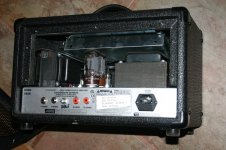
My tool of choice is a simple stud finder, this is one of my build's that may seem at first to defy logic.
Xfrmr of choice is:http://pactran.com/industry-solutions/guitar-amplifiers/
Xfrmr of choice is:http://pactran.com/industry-solutions/guitar-amplifiers/
Attachments
- Status
- This old topic is closed. If you want to reopen this topic, contact a moderator using the "Report Post" button.
- Home
- Amplifiers
- Tubes / Valves
- Tube/Transformer Positioning on Chassis