When planning the positioning of Power tubes (300b's, KT88's, etc.) on the top of the chassis, is it more important to keep them as far away from the preamp tubes (12AX7 or ecc88) as possible, or the transformers (in terms of noise suppression)?
Also, what about tube rectifiers? Is it ok to place one in between 2 transformers?
One more question: Is a tube rectifier such as a 5ar4 a full-wave rectifier or do I need 2 to perform that duty? Is it important to have full-wave rectification in a class A phono preamp/headphone amp?
Thanks
Also, what about tube rectifiers? Is it ok to place one in between 2 transformers?
One more question: Is a tube rectifier such as a 5ar4 a full-wave rectifier or do I need 2 to perform that duty? Is it important to have full-wave rectification in a class A phono preamp/headphone amp?
Thanks
You want to keep your wires short. Power valves want to be next to their output transformer, and will not mind being near to a mains transformer. Pre-amplifier valves want to as far away from mains transformers as possible (whose coils should be pointed at a right angle to these valves). Valve rectifiers should be close to their mains transformer with very short wiring to their capacitor, and should always be full-wave.
5AR4/GZ34 contains two diodes and will allow full-wave rectification with a centre-tapped transformer, or, if you add a pair of silicon diodes, you can make a bridge, which allows an ordinary transformer to be used.
5AR4/GZ34 contains two diodes and will allow full-wave rectification with a centre-tapped transformer, or, if you add a pair of silicon diodes, you can make a bridge, which allows an ordinary transformer to be used.
Hybrid Rectumfrier.
Hi,
Works with a CT xformer as well.
Cheers,")
Edit: this actually works best with a CT Xformer, people should really try this it really good.
Hi,
you can make a bridge, which allows an ordinary transformer to be used.
Works with a CT xformer as well.
Cheers,
Edit: this actually works best with a CT Xformer, people should really try this it really good.
Another thing you might want to consider is heat. Make sure you have at least half an inch or more around the rectifier and power tubes so that air can circulate.
Re: hybrid diode/tube rectification, I plan to try this at some stage, using UF4007 high speed diodes and a 5V4, you get the benefits of slow warm up and no "switching" noise (which I have never been able to hear anyway )
Re: hybrid diode/tube rectification, I plan to try this at some stage, using UF4007 high speed diodes and a 5V4, you get the benefits of slow warm up and no "switching" noise (which I have never been able to hear anyway
)EC8010 said:Pre-amplifier valves want to as far away from mains transformers as possible (whose coils should be pointed at a right angle to these valves).
.
What do you mean by that? (..not the biggest possible distance between the input tubes,this is obvious!)
I mean,what's this "right angle" thing?
I know about the 90 degrees alignament of the PS trans,choke(s) and OPT,and also of aligning the anodes of output beam tetrodes to 90 degrees relative to PS,but what you said is new to me.
Did you also meant some kind of "3D" arrangement of the coils (laminations) to achieve that?

Right angles to reality
The leakage field of a coil (transformer or choke) is strongest along its axis, so if you draw a line from the centre of the coil to your input valve, the coil should be aligned at right angles to this line.
We've both learned something here, because although I can instantly see the logic, I had not considered the relative alignment of beam tetrodes and power transformers.
It's worth bearing in mind that output transformers have far less leakage flux than mains transformers because output trnasformers are designed to minimise leakage inductance. This means that you can almost do what you like with output transformers relative to valves.
Le Basseur said:...and also of aligning the anodes of output beam tetrodes to 90 degrees relative to PS, but what you said is new to me.
The leakage field of a coil (transformer or choke) is strongest along its axis, so if you draw a line from the centre of the coil to your input valve, the coil should be aligned at right angles to this line.
We've both learned something here, because although I can instantly see the logic, I had not considered the relative alignment of beam tetrodes and power transformers.
It's worth bearing in mind that output transformers have far less leakage flux than mains transformers because output trnasformers are designed to minimise leakage inductance. This means that you can almost do what you like with output transformers relative to valves.
the empirical method
Since we are trying to minimize magnetic coupling between components, I suggest that we actually do a few measurements. For a set of monoblock SE amps I'm starting one, I mounted the power transformers on the chassis and hooked them up with AC power. Then I positioned the output transformers roughly where I wanted them on the chassis and measured the induced AC voltage on them with my DVM. Moving the output transformers around allowed almost complete cancellation of the induced voltage and the optimum position was not with the transformers at 90 degrees to one another. Instead things were better when the angle was a shifted about 10 degrees off of 90.
Theory is great but nothing beats reality.
---Gary
Re: the empirical method
EC8010 said:
The leakage field of a coil (transformer or choke) is strongest along its axis, so if you draw a line from the centre of the coil to your input valve, the coil should be aligned at right angles to this line.
OK,I knew that,but I thought it's some other "snake oil" solution...
We've both learned something here, because although I can instantly see the logic, I had not considered the relative alignment of beam tetrodes and power transformers.
OK,her's the beam tetrode issue:
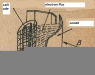
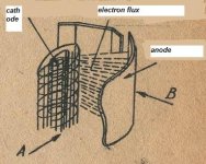
As you noticed,the geometry of an anode resembles an oval or rectangle.If you look at the attached picture,you'll consider the two axis,A and B.Well,the magnetic field shouldn't be along the A axis,or intersect them in any way,because in this case the hum increases.Alike,the best position of a tetrode is with the B axis and the trannsformer's flux paralleled.
.
Attachments
EC8010 said:
The leakage field of a coil (transformer or choke) is strongest along its axis, so if you draw a line from the centre of the coil to your input valve, the coil should be aligned at right angles to this line.
OK,I knew that,but I thought it's some other "snake oil" solution...
We've both learned something here, because although I can instantly see the logic, I had not considered the relative alignment of beam tetrodes and power transformers.
.
OK,her's the beam tetrode issue:
As you noticed,the geometry of an anode resembles an oval or rectangle.If you look at the attached picture,you'll consider the two axis,A and B.Well,the magnetic field shouldn't be along the A axis,or intersect them in any way,because in this case the hum increases.Alike,the best position of a tetrode is with the B axis and the transformer's flux paralleled.
Sorry for the mess,something's wrong with IP!


to clarify
In case I wasn't clear in my earlier post (its early morning in NY), even though I was explaining how I positioned the output transformer relative to the power transformer in my amps, the point was that one can actually measure the magnetic field from a power transformer by measuring the coupling into another magnetic component such as a choke or another transformer. Thus you can sniff around and see where the magnetic field is weakest and put your tubes in that location.
---Gary
Re: to clarify
OK,AgryB,read you loud and clear!
GaryB said:In case I wasn't clear in my earlier post (its early morning in NY), even though I was explaining how I positioned the output transformer relative to the power transformer in my amps, the point was that one can actually measure the magnetic field from a power transformer by measuring the coupling into another magnetic component such as a choke or another transformer. Thus you can sniff around and see where the magnetic field is weakest and put your tubes in that location.
---Gary
OK,AgryB,read you loud and clear!
Re: the empirical method
Absolutely. I've measured for optimum relative positioning between transformers, rather than looking for a quiet place as you've suggested for valves. It must be time for the search coil to come out again!
GaryB said:Theory is great but nothing beats reality.
Absolutely. I've measured for optimum relative positioning between transformers, rather than looking for a quiet place as you've suggested for valves. It must be time for the search coil to come out again!
english lesson
Hmmm.....
I am truly sorry that I must ask this question, because I understand that the answer was clear, BUT my lack of english maks me confused.....
"whose coils should be pointed at a right angle to these valves"
To me that could be just anything... (if I turn it 90 deg, its still right angle...or??) Is there any scheth or easy drawing that explains this for a non englih speaking dumb swede?
Also: Whats the pro and cons of using aluminum vs steel. Steel is magnetic is that good or bad? Will it absore the magnetic field or will it take the field to places were I don't want it? I think theres something called my-metal (u-metal) but thats out of reacf for me.
Thanks a lot
björn
--> björn!
http://home.swipnet.se/sm6xun/gear/x-former.bmp
this picture should describe the problem, a transformer has a magnetic flux surrounding the core, that will cause hum if your transformer isn't shielded with, for example, µ-metal (my-metall)
-this is what GARY_B meant with his 90º degrees angle...
in swedish: rören bör inte monteras i "kortänden" på trafon, utan på sidan..hoppas att ritningen är förklarar!
-lycka till!
when doing magnetic shielding, i prefer thin coppersheets, solderable and easy to work with, pretty good shield too, better than aluminium anyhow.
Mr. Triatic or may I adress u xun?:
Very easy to understand your drawing. Thank u very much or in swedish:
Tack så mycket.
But I'm still puzzled over that I read some where that the power-supply transformer and the output tranny should be 90 deg apart. Is it so and than why? .To cancel out the fields ..or?
And where can I take up some more info on the metal-stuff?
cheers,
björn
ShiFtY said:Another thing you might want to consider is heat. Make sure you have at least half an inch or more around the rectifier and power tubes so that air can circulate.
Re: hybrid diode/tube rectification, I plan to try this at some stage, using UF4007 high speed diodes and a 5V4, you get the benefits of slow warm up and no "switching" noise (which I have never been able to hear anyway
Hi ShiFtY,
Can you tell me/us more about the hybride rectifications using the UF4007?
Thanks in advance,
Audiofanatic
HYBRID RECTIFIER.
Hi,
It works with any pair of diodes, really:
Cheers,
Hi,
Can you tell me/us more about the hybride rectifications using the UF4007?
It works with any pair of diodes, really:
Cheers,
Attachments
Re: --> björn!
I hate to say it, but that diagram is wrong. The lines of flux shown are incomplete, and do not show the straight line that comes out of the axis of the coil. Valves should not be on the axis of the coil.
Steel can be a problem. If you mount a toroid or a drop-through transformer on steel, flux will be carried to places you don't want. This is the reason why some amplifiers mount drop-through transformers on plastic spacers. The spacers are effectively a magnetic resistance, and prevent flux from entering the steel chassis.
Mr. Triatic said:
I hate to say it, but that diagram is wrong. The lines of flux shown are incomplete, and do not show the straight line that comes out of the axis of the coil. Valves should not be on the axis of the coil.
Steel can be a problem. If you mount a toroid or a drop-through transformer on steel, flux will be carried to places you don't want. This is the reason why some amplifiers mount drop-through transformers on plastic spacers. The spacers are effectively a magnetic resistance, and prevent flux from entering the steel chassis.
- Status
- This old topic is closed. If you want to reopen this topic, contact a moderator using the "Report Post" button.
- Home
- Amplifiers
- Tubes / Valves
- Tube/Transformer Positioning on Chassis