If the LTP is the first stage, as in an all-differential amp, then the alternative to a negative supply woud be to bias up the grid that doesn;t receive the signal and ground it through a capacitor, Connect that grid to the input grid via a 1 Meg resistor and use capacitor-coupling for the input.
If the CCS is made up of BJTs, such as the simple and effective cascode CCS favored by Morgan Jones, you would need a negative supply of about -40v, or you could bias up the grids by 40v. Clearly, the negative supply solution does avoid the need to elevate B+ by about 40v but that's bot really a lot to worry about.
I don't see any other advantage to using a negative supply with an SS CCS but I can see a disadvantage in having to provide a negative supply itself. Of course, if you want a pentode CCS, it's a different story, because that will require over 100v to operate!
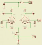
...if I may take advantage of this thread for a beginner's question, is it correct in the attached schematic to put something like -10V or -15V to get a few mA out of the JFET?
(The place where I copied it only mentions "a small negative supply", but what is "small" when handling vacuum tube supplies? the B+ here is 300V...)
By the way, the triodes are ECC88.
And the whole thing should provide opposite phases out of C1 and C2.
Thanks.
_
(The place where I copied it only mentions "a small negative supply", but what is "small" when handling vacuum tube supplies? the B+ here is 300V...)
By the way, the triodes are ECC88.
And the whole thing should provide opposite phases out of C1 and C2.
Thanks.
_
Attachments
ray_moth said:
I don't see any other advantage to using a negative supply with an SS CCS but I can see a disadvantage in having to provide a negative supply itself. Of course, if you want a pentode CCS, it's a different story, because that will require over 100v to operate!
The 100V is an approximation, average likely tube choice etc. It is easy to see a 200 mA CCS that only needs 60V to operate with; with 100V, 500 mA is quite easy...
")
cheers,
Douglas
but I can see a disadvantage in having to provide a negative supply itself.
Exactly the reason why I'm asking.
If the CCS is made up of BJTs, such as the simple and effective cascode CCS favored by Morgan Jones, you would need a negative supply of about -40v, or you could bias up the grids by 40v.
Thanks, that should help me along the way.
Simon
A battery biased, or self-biased MOSFET ccs made from Supertex depletion-mode MOSFET's like DN2540N5 and DN3545N3 are good with about 15V of headroom; the capacitance change is mostly over by ~10V.
Have you got a schematic?
Simon
Simon,
A big advantage to using a B- supply is the elimination of caps. in the signal path. Only the couplers between LTP and "finals" are present. Fewer phase shifts imply much greater stability.
Look at the "El Cheapo" schematic. The CCS shown is a MOSFET cascode devised by Doug (Bandersnatch).
A big advantage to using a B- supply is the elimination of caps. in the signal path. Only the couplers between LTP and "finals" are present. Fewer phase shifts imply much greater stability.
Look at the "El Cheapo" schematic. The CCS shown is a MOSFET cascode devised by Doug (Bandersnatch).
Hi Klimon
Here you go:
http://www.diyaudio.com/forums/showthread.php?postid=1603111#post1603111
If you want I can sell you a couple of DN2540's IC's, for 2,50 euro/each.
Erik
Here you go:
http://www.diyaudio.com/forums/showthread.php?postid=1603111#post1603111
If you want I can sell you a couple of DN2540's IC's, for 2,50 euro/each.
Erik
Simon,
Take a look at Bonavolta's phase splitter page. The long tailed pair drawing is right out of a Mullard 5-20. Notice C3. The next drawing, Schmidt (should be Schmitt), is even more illustrative. Eliminate CG1 and CG2. Ground RG1 and RG2. Replace RK1 and RK2 with a CCS and a B- rail. Voilla, you have the "El Cheapo" splitter/driver. Since his "Musical Machine" does not use loop NFB, Poindexter simply grounds the non-inverting grid.
All of these things are variations on the differential gain block theme.
Ok, sorry for the short delay. Thanks for the explanation Eli. Meanwhile Erik helped me to some Dn2540's and I'm set on using Sy's cascode as linked supra. Still some questions about biasing though. It's clear to me how the resistors set the CCS current. Supposing I won't use a B- supply, I presume the cathode-anode voltage equals B+ voltage minus about 10volts used by the CCS, right? That also implies that the grid will be at -10v with regards to the cathode... To set it to the about -1,5V bias my tubes require, how should I proceed?
Does this make any sense?
Muchos gracias
Simon
Does this make any sense?
Muchos gracias
Simon
Rereading the beginning of Ray Moths post I'm getting the impression it might be worthwile to use a B- supply after all... Maybe tapping B- from the same trafo as B+, e.g. the way tubelab does for biasing the output stage in his tubelab SE, is a viable and simple alternative?
http://www.tubelab.com/TubelabSE.htm
Thanks,
Simon
http://www.tubelab.com/TubelabSE.htm
Thanks,
Simon
Hi Simon,
Yes, it's viable - one of the advantages of a center-tapped secondary using full-wave rectification for B+.
It wouldn't work for an untapped secondary using a bridge rectifier, but you could always buy a small, inexpensive additional power tranny to supply the negative voltage for the small amount of current needed.
ray_moth said:Hi Simon,
Yes, it's viable - one of the advantages of a center-tapped secondary using full-wave rectification for B+.
It wouldn't work for an untapped secondary using a bridge rectifier, but you could always buy a small, inexpensive additional power tranny to supply the negative voltage for the small amount of current needed.
hey-Hey!!!,
The $6/25.2 volt, 450 mA Radio Shack TX works very well here. Either a full bridge across it for bias and CCS or a doubler. Bias to the doubled voltage, and ccs to the middle is my method.
cheers,
Douglas
- Status
- This old topic is closed. If you want to reopen this topic, contact a moderator using the "Report Post" button.
- Home
- Amplifiers
- Tubes / Valves
- Negative LTP CCS supply