Hi,
The attached picture shows a comparison between a buffer used at high voltage +/-85V and another at +/-15V.
I would like to know, how do we scale the respective R1 and R2 to suit the supply voltage, particularly I would like to do something at +/-40V.
Thanks.
The attached picture shows a comparison between a buffer used at high voltage +/-85V and another at +/-15V.
I would like to know, how do we scale the respective R1 and R2 to suit the supply voltage, particularly I would like to do something at +/-40V.
Thanks.
Attachments
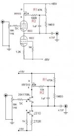
Maybe nobody's replying because like me they don't think 80V is enough to do a great job across 2 6922's. Why don't you step back and tell us what you are trying to accomplish? +/-40V is fixed, we know that. How about tube type, 6922's? Does it have to be a cascode: what voltage swing and load impedance do you have to drive?
You're right I didn't state my goal correctly.
I'm trying to strike an design which is inbetween both, whereby I will use 1 half of the 6922 per channel (to save on tubes whereby I only use 1 tube for stereo - I'm building a 6 channel buffer for my DCX2496) and I want to use a +/-40V supply (as I have the required trafo and plenty of PanFC 1000uF 50V caps) and I would like the idea of having a 2sK CCs on the bottom of the 6922 and attaching the IRF610 at the anode.
Hence my question, how do I scale the R1 and R2 to suit a +40V supply given that for a +85V R1 and R2 are 47K & 100R wherelse at +15V R1 and R2 are 470K & 10K respectively.
Hope it's clear now.
OK, here is the science behind the whole circuit. The implementation is up to the user. I am of the opinion that +40 volts isn't quite enough, but I haven't tried it, and I tend to use too much voltage rather than not enough.
First off, this isn't really a true cascode, the gate (grid) of the top device isn't grounded. It is a stripped down version of the "augmented cathode follower" circuit invented (and patented) by Macdonald in 1957. It is very similar to the FVP circuit used in Vacuum State preamps. I have spent some time experimenting with this design, but for output stage use.
There are 3 devices, any or all of them can be tubes or mosfets. Each has a seperate function.
The middle device is a cathode or source follower. Any active device has parameters that vary with the applied voltage or current through the device. This circuit does a good job of removing those variations by fixing the applied voltage and current through the follower.
The bottom device is a CCS. The cathode (1.2K) or source (270 ohm) resistor sets the current through the entire circuit. The value of the resistor is determined by the characteristics of the bottom device. It can be determined from the device curves or by experimentation. The gate or grid resistor is just a stopper and is there to prevent oscillation. A CCS IC can be used here instead of the fet or tube. The negative supply voltage must be high enough for the chosen device to operate as a decent CCS. 40 volts isn't going to work with a 6922, but is OK for the fet or IC.
The top device is another follower that is used to keep a constant voltage across the main follower device. The audio voltage is coupled to the gate via the 1uF capacitor so that the source voltage moves with the signal but the average voltage (which is the plate voltage for the main follower) is set by the ratio of the 1MEG resistor and R1. R2 is again a stopper whose value is determined by the stability requirements of the fet in use. I would start with 1K.
Now you have 40 volts of B+ which is divided between the main follower tube, and the mosfer buffer. I would give the tube most of the voltage, but make sure the fet has enough to accomodate the full volume audio swing without clipping. You could think about this a lot, plot some curves, hammer on the calculator, and maybe come up with something. The problem is how much current will be needed or available from a 6922 at 25 volts? I would put a variable resistor in the source of the CCS, and a 1MEG pot in place of both the 1MEG and R1. Then hook up a scope and turn some knobs.
Thank you sir for your clear and concise explanation !
Attached herewith is my interpretation or rather my effort to understand the circuit and to improvise to suit whatever that's in my junkbox.
With the +40Vsupply going thru the voltage divider between 100K and 1 Meg there's 4V aross the mosfet and the remaining 36V to the 6922. I calculated that 4V to 5V across the mosfet is done on both circuits I showed earlier.
On the bottom portion I'll add the 2SK170 (which I also happen to have) and then I'll add a pot and tune the current across the 6K8 resistor at 10mA setting its bias.
Please feel free to comment.
Attachments
- Status
- This old topic is closed. If you want to reopen this topic, contact a moderator using the "Report Post" button.