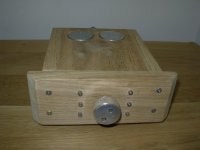
Not sure this is the right section but I have just finished building a tvc using Sowter 9355 transformers with occ windings and Elma 23 way switch, the results of which are nothing short of gob smacking!
I was hoping for a small degree of improvement but it hascompletely transformed my system.It has added dynamics, rhythm an pace, seperated out the individual strands of music even on loud complex passages, seems to have increased dynamic range, removed all traces of "digital glare" making my old Meridian multibit cd player sound very relaxed and smooth it has even removed what I always thought of as intermodulation, example electric piano on track 2 of Crime of the Century which has always sounded intermodulated on every system I have owned on both cd and record since bying the album in 1974!
To get to the point, what from a technical point of view is the mechanism for all this?
My previous vc was a passive attenuator with Vishays and Holcos and that was obviously better than tha previous Alps pot, but this is a huge improvement, in fact the biggest single improvement I have ever made.
Impedance matching springs to mind but the previous attenuator was 20k into 100k 6922 front end so its hard to see how that was a problem. Resistor noise compared to yards of wire maybe? How could these things effect separation, transparency, dynamics etc?
Dont get me wrong Im more than happy with the result but not fully understanding how this works is A) driving me nuts, B) making me wonder how I can continue to design and build my own equipment without a better grasp of how things work.
All comments would be gratefuly recieved.
Regards, gsd
PS apart from all the above it also works as a volume control!
Attachments
1.
The length of the windings in the volume control are exactly matched in left and right channels, which greatly enhances overal system performance.
2.
The action of introducing a transformer at the input (even if not a Transformer Volume Control) does two things; A) breaks ground current loops which may have previously been significantly degrading the performance, B) passively filters out any high frequency noise which may have affected subsequent amplifier stages.
Thanks for the reply.
The previous attenuator resistor values were hand selected from a large stock for very tight matching. I also wondered about filtering effects but I have previously experimented with passive filtering post volume control with negative effects.
You would actually think that the tvc has increased the bandwith from listening.
Grpund loops may be on the right track . I chose the Sowter 9335 because unlice others it has a primary winding, and I am connecting the cd players output in semi balanced mode so that the cd player is floating without a ground connection between cd player and amp.
Perhaps someone may have further ideas on this or other posibilities.
Regards, gsd
gsd said:How could these things effect separation, transparency, dynamics etc?
A remarkable post. Either TVCs really differ much more from each other than resistor attenuators or listener's reactions are completely random and unpredictable. My old TVC had problems in all the listed areas and more. It was not completely unlistenable as it had quite a pleasant colouration but it was a disappointment from day one.
Great that it works for you. Have you tried it with analogue sources? Maybe it's abilities to remove digital noise are particularly useful in your system.
There are differences between tvc's basicaly two types. 1 a tapped auto transformer and 2 a proper transformer with a primary winding and tapped secondary. The ones I am using have an isolated primary winding which as Gordy has pointed out prevents ground loops (depending on how you wire it)
I'm not yet sold on the filter effect for reasons already mentioned and of course the cd player has extensive filtering of its own.
The effects on my system are not just subjective.My diy hifi's biggest critic(my wife) who never lets me off easy on the sound quality of the system commented that it immediatly sounded much more relaxed and musical as if I had replaced the entire system!
The old attenuator was obviously holding back the system but to that degree has shocked me.
Im afraid I no longer have analogue to try so can only comment on the sound via cd.
Regards, gsd
gsd said:The ones I am using have an isolated primary winding which as Gordy has pointed out prevents ground loops (depending on how you wire it)
Well, if you do call it a TVC it is obviously not an autoformer. Ground loops should not exist in a properly (with respect to audio) grounded system anyway. What it certainly does is isolating the noisy ground of your cdp from your amp. Btw, what is the input impedance of your amp and the value of your resistive attenuator? Is it a tube amp?
Interestingly, my TVC sounded marginally better connected as an autoformer, ie isolation did nothing to improve the sound. It is an experiment you can also easily do: either common the input/output grounds or connect it as an autoformer. It will be interesting to get your subjective assessment and even more interesting the "objective" verdict of your wife
")
Sorry for the incorrect terminology but both types seem to be commonly called tvc's
My amplifier is valve/ mosfet hybrid. The front end is 2 pairs of 6922's configured completely open loop with cathode followers driving a compound transistor/fet source follower output stage again open loop but with an error correction circuit around the output pair. There are 4 o/p stages in total providing bi-amping. All sections have seperate regulated supplies exept the o/p pair which are unregulated.
Most resistors are Vishay bulk foil and most caps are Solen polyprops. The amps were built for minimal signal path.
As stated in the original post the resistor attenuator was 20k and the i/p impedance of the amp around 100k.
Maybe the difference is down to the occ copper windings?
The more thought I give this the less certain I am that the ground noise from the cd is isolated as it must still appear acros the primary winding of the tvc.
Regards, gsd
The TVC has some obvious technical advantages compared to the resistive attenuator. If your amp input stage is just a common cathode then there is a substantial Miller capacitance to drive. The attenuator worst case output is 5k and the TVC probably around 400ohm. If you listen to the attenuator around the full volume position then this is less of an advantage. The TVC starts filtering above 120kHz which is much lower than the attenuator.
Have you ever tried a good active preamp? Possibly a single triode, choke or transformer loaded following your attenuator?
Have you ever tried a good active preamp? Possibly a single triode, choke or transformer loaded following your attenuator?
The miller capacitance is around 50pf which with the worst case for the attenuator gives f-3db of around 150khz I'm not sure of the o/p impedance of the tvc as I dont know the o/p impedance of the cd player but as you indicate it would certainly result in a higher f-3db point, but either way both are considerably out of my hearing range.
I havnt recently tried a pre but have previously used a valve buffer after the attenuator.I stopped using it (the buffer) as it had a negative impact on sound quality
The attenuator sounded better on its own.To my hearing less (in the signal path) is more.
Regards, gsd
I havnt recently tried a pre but have previously used a valve buffer after the attenuator.I stopped using it (the buffer) as it had a negative impact on sound quality
The attenuator sounded better on its own.To my hearing less (in the signal path) is more.
Regards, gsd
What he said about the output impedance of a TVC. Much less than a resistive one.
Also, a resistive attenuator attenuates by dissipating energy. A TVC does not do this (other than incidental wire resistance, etc., or insertion loss).
Thus, the full power of the signal remains at reduced voltage, but higher available current. This probably helps the S/N ratio.
Also, a resistive attenuator attenuates by dissipating energy. A TVC does not do this (other than incidental wire resistance, etc., or insertion loss).
Thus, the full power of the signal remains at reduced voltage, but higher available current. This probably helps the S/N ratio.
gsd said:I havnt recently tried a pre but have previously used a valve buffer after the attenuator.
If a valve buffer means a cathode follower i am not surprised you didn't like it. A transformer/choke loaded common cathode stage sounds completely different.
Thanks for that poogle.The energy dissipation could be a good explanation.It may explain for instance why the tvc sounds similar at all volume levels whereas the attenuator ( or pot) tends to loose dynamics at lower volume levels.
I have also begun to think about the rectification effects of metal contacts which in the case of a ladder resistor network is large with switch to resistors, resistors to resistors and resistor end caps.
I presume this would have a much greater effect on low level portions of the signal.
Perhaps this may partially explain preferences for shunt attenuators or alternative designs like the Lightspeed.
Regards, gsd
pooge said:What he said about the output impedance of a TVC. Much less than a resistive one.
Also, a resistive attenuator attenuates by dissipating energy. A TVC does not do this (other than incidental wire resistance, etc., or insertion loss).
Thus, the full power of the signal remains at reduced voltage, but higher available current. This probably helps the S/N ratio.
I'm not convinced by this. Resistors anywhere in a circuit dissipate energy - it's how they work! Anode loads are the prime example: for a common-cathode circuit to have minimum distortion the anode voltage should be around half of the HT voltage, so half the signal voltage ends up heating the resistor. In an active circuit with a power supply, power is not a significant issue.
Single-ended output stages tend to have very natural, immediate dynamics, even though at least three-quarters of the power they receive from the HT supply ends up as heat.
I'm not saying that TVCs don't sound good - just that this is unlikely to be the reason!
Alex
Hi alex
I thought the explination may have some merit as the lost power dissipated is signal as opposed to power supply dissipatoin.The heat generated in say a single ended o/p stage happens without any signal present.
Its certainly worth more thought unless someone has a better explination.
Regards, gsd
I thought the explination may have some merit as the lost power dissipated is signal as opposed to power supply dissipatoin.The heat generated in say a single ended o/p stage happens without any signal present.
Its certainly worth more thought unless someone has a better explination.
Regards, gsd
Alex M said:
Anode loads are the prime example: for a common-cathode circuit to have minimum distortion the anode voltage should be around half of the HT voltage, so half the signal voltage ends up heating the resistor.
The simple counter-argument to this is that replacement of anode loads with chokes/transformers or active CCSs generally leads to improved perceived sound. And similarly replacing cathode resistors with fixed voltage sources.
It's kind of easy to support almost any argument in audio. And any counter-argument.
It is also much easier to prove that TVCs stand no chance of sounding good with hysteresis, distortion and phase issues
analog_sa said:
The simple counter-argument to this is that replacement of anode loads with chokes/transformers or active CCSs generally leads to improved perceived sound. And similarly replacing cathode resistors with fixed voltage sources.
It's kind of easy to support almost any argument in audio. And any counter-argument.
It is also much easier to prove that TVCs stand no chance of sounding good with hysteresis, distortion and phase issues
I think I agree with you but, although active loads and transformers both substantially reduce distortion if used appropriately, they do so for rather different reasons (I use active loads in all my line-level circuits). Allen Wright maintains that transformers are not the ultimate technology in audio, though I have very little practical experience in this area.
All the same, active loads definitely dissipate signal: a constant current circuit will dissipate linearly with signal amplitude, whereas a resistor in most places will dissipate as the signal amplitude squared. Transformers need to be terminated correctly for linear frequency response, which normally means a resistor.
I also agree that it is easy to support or demolish almost any claim in audio, and generalisations are almost always wrong (except this one).
Alex
analog_sa said:A good CCS may have impedance in the Gohm region; how much signal can this dissipate?
Good point.
analog_sa said:None of the good transformers require resistive termination. Those that do often sound better unterminated anyway.
I didn't know that. My experience and understanding of signal transformers has been mainly with output transformers and MC step-ups, both of which defintely need appropriate termination.
I just had a look at Lynn Olsen's Aurora and Raven circuits, and indeed neither of those have resistive termination.
Alex
- Status
- This old topic is closed. If you want to reopen this topic, contact a moderator using the "Report Post" button.
- Home
- Amplifiers
- Tubes / Valves
- Transformer volume control questions.