This is my first tube project and may be my last too.....
After 2 years of reading and trying to understand how valves work, I finally built my Aikido Preamp. I used John Broskie's octal board with 6sn7 input and output. Mr. Bas' Tube HV power supply board and Mikkel's attenuator with display and remote functions. All were kits.
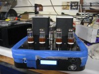
The build went well and it looks GREAT!
There is a weird fuzziness to the sound, but not a crackle, almost like a poorly tuned AM radio station. It's not a hum or a buzz that would be associated with a transformer noise or AC related electrical field. More like being too close to a microphone kinda fuzzy. Think drunk DJ with a cheap microphone at a wedding kind of fuzzy. I can hear the clarity of the music in the background but it's
hidden by the fuzz.
I think it's a grounding issue somewhere, but I've tried every possibility I can think of and I need help. I just don't know enough to get this working right. I'm very frustrated.
Signal input and output grounds are isolated from the chassis, thanks Gregg; (AKA Geek)
I have run a wire from the -Ve to the chassis...no difference.
I've checked the solder joints on the attenuation board.....nope.
Solder joints on the Aikido board......nope.
I've bypassed the attenuation board altogether..........nope.
I've checked the voltage of B+ , the B+ bias, Heaters and jumpers on the board.....all are fine.
I've replaced the rectifier tube ..........nope.
I've removed the output caps and used .33 PIOs instead......nope.
I'm out of ideas and could use some help. Please.
Any inputs or ideas you may have will be appreciated. I'm happy to give anything a try. But, I am a newb, so speak/type slowly.
Failing my own attempts at finding the cause:
I live in the Sacramento area and would be happy to provide your favorite beverage for a hands on look if you could spare some time. I'll drive, just give me directions and what beverage you would like.
I know there is someone in Davis that is a valve lover, I just cannot remember whom it is to directly beg their help.
I've attached a link to a sound file hosted elsewhere on the net.
Fuzzy sound file
Make sure to click the "Skip this Ad" at the top of the PoP UP window.
It's taped up so I don't scratch the Carbon Fiber while working on it.
The top I powder coated at home, mods for the PC gun I posted on this website.
Thanks for the helping hand,
Ron
edited several times .....'cause I care!
After 2 years of reading and trying to understand how valves work, I finally built my Aikido Preamp. I used John Broskie's octal board with 6sn7 input and output. Mr. Bas' Tube HV power supply board and Mikkel's attenuator with display and remote functions. All were kits.
The build went well and it looks GREAT!
There is a weird fuzziness to the sound, but not a crackle, almost like a poorly tuned AM radio station. It's not a hum or a buzz that would be associated with a transformer noise or AC related electrical field. More like being too close to a microphone kinda fuzzy. Think drunk DJ with a cheap microphone at a wedding kind of fuzzy. I can hear the clarity of the music in the background but it's
hidden by the fuzz.
I think it's a grounding issue somewhere, but I've tried every possibility I can think of and I need help. I just don't know enough to get this working right. I'm very frustrated.
Signal input and output grounds are isolated from the chassis, thanks Gregg; (AKA Geek)
I have run a wire from the -Ve to the chassis...no difference.
I've checked the solder joints on the attenuation board.....nope.
Solder joints on the Aikido board......nope.
I've bypassed the attenuation board altogether..........nope.
I've checked the voltage of B+ , the B+ bias, Heaters and jumpers on the board.....all are fine.
I've replaced the rectifier tube ..........nope.
I've removed the output caps and used .33 PIOs instead......nope.
I'm out of ideas and could use some help. Please.
Any inputs or ideas you may have will be appreciated. I'm happy to give anything a try. But, I am a newb, so speak/type slowly.
Failing my own attempts at finding the cause:
I live in the Sacramento area and would be happy to provide your favorite beverage for a hands on look if you could spare some time. I'll drive, just give me directions and what beverage you would like.
I know there is someone in Davis that is a valve lover, I just cannot remember whom it is to directly beg their help.
I've attached a link to a sound file hosted elsewhere on the net.
Fuzzy sound file
Make sure to click the "Skip this Ad" at the top of the PoP UP window.
It's taped up so I don't scratch the Carbon Fiber while working on it.
The top I powder coated at home, mods for the PC gun I posted on this website.
Thanks for the helping hand,
Ron
edited several times .....'cause I care!
Attachments
Looks great.
From someone who has had their fair share of problems as they build.... take a step back, find your innner calm (! I'm not a hippy honest!) and then remove your emotions from it (hence your frustrations). Then start logically to work through it step by step. I honestly don't mean to sound glib, its just I know exactly how you feel!!
Or you could ignore all that and post a few upskirt pics! (a good idea anyway)
Beautiful chassis and build though.
Fran

Consider a minimalist approach. Can you disconnect your attenuator PCB (I'm assuming it's the board with the sand all over it), input selector, etc. and just run one set of RCA inputs into a simple vol pot and then to the Aikido PCB and out?
This "stripped down" config will let you figure out if it is related to the Aikido boards or something else.
This "stripped down" config will let you figure out if it is related to the Aikido boards or something else.
BW,
I do not have an input selector, so that makes it somewhat easier...LOL
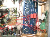
Yes, the attenuator is the sandy unit with the foam underneath to quiet the clackity - clack of the relays. I have tried as you suggested, bypassing the attenuator completely using a very quiet song straight from the CD player to the RCA jacks, then Aikido board's inputs, from the outputs; straight to the RCA jack out to the good 'Ol Haffler amp. same effect........Fuzzy. Heell, I didn't even use a pot and it's still fuzzy
Sorta pointing to the Aikido board, huh....
If a choke makes a PS ring...what does that sound like??? And could that be heard as fuzzy on the signal side.
I have a 8.5 H choke on the Mr. Bas' PS board.
I'll strip her down again tomorrow and try it again, maybe I missed something. (DUHH)!
Thanks for the help,
Keep'em coming.
Ron
I do not have an input selector, so that makes it somewhat easier...LOL
Yes, the attenuator is the sandy unit with the foam underneath to quiet the clackity - clack of the relays. I have tried as you suggested, bypassing the attenuator completely using a very quiet song straight from the CD player to the RCA jacks, then Aikido board's inputs, from the outputs; straight to the RCA jack out to the good 'Ol Haffler amp.
same effect........Fuzzy. Heell, I didn't even use a pot and it's still fuzzySorta pointing to the Aikido board, huh....
If a choke makes a PS ring...what does that sound like??? And could that be heard as fuzzy on the signal side.
I have a 8.5 H choke on the Mr. Bas' PS board.
I'll strip her down again tomorrow and try it again, maybe I missed something. (DUHH)!
Thanks for the help,
Keep'em coming.
Ron
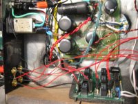
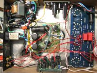
The board with the yellow twisted wires is a rectifier from Broskie that supplies 12.6V DC to the heaters...which are in series to 6.3V.
The other board with the green twisted wiring is a rectifier and a 5V DC regulator for the Display and the attenuator board.
BTW, Mr. Bas' board sits on top of an ABS plastic board with standoffs.
I DO appreciate the help.
Thanks,
Ron
The other board with the green twisted wiring is a rectifier and a 5V DC regulator for the Display and the attenuator board.
BTW, Mr. Bas' board sits on top of an ABS plastic board with standoffs.
I DO appreciate the help.
Thanks,
Ron
Is there any possibility that DC is going wrongly to some relay audio contact or somewhere in the Aikido that it should not be present? Like to the hum canceling grid feed or the output, due to some problematic cap? Sounds like chopping DC biased signal. I would inspect everything for proper execution starting from the attenuator. You reminded me of a classic album by the way. Gonna spin it on my TT first thing tomorrow.
Attachments

Salas,
Thank you for taking the time (and concern) to listen to the .wav file.
It does sound like distortion even at low volume.
I have tested the attenuation circuit by removing it completely from the preamp. Fuzzy still. With that in mind it SEEMS likely that the problem lies in the Aikido Board itself. More correctly the way I built it wrong.
Should there be any DC voltage other than in the heater circuit?
I think I remember about 30V DC from the +Signal out to chassis.
Thanks for the clues on what to look for.
Enjoy your Vinyl. I can't wait to hear Alison Krauss through the Aikido.
Thanks,
Ron
Renron said:Should there be any DC voltage other than in the heater circuit?
I think I remember about 30V DC from the +Signal out to chassis.
Thanks,
Ron
That strengthens the scenario that there is AC signal riding on DC and getting clipped. Please examine the Aikido build thoroughly for correctness.
JPS said:Try running heaters with AC supply instead of DC.
I will try AC heaters as a last resort, because it requires desoldering 4 caps on the heaters. However I have heard (read) that AC heaters sound better than DC on the heaters. Is this subjective opinion or audible fact?
salas said:
That strengthens the scenario that there is AC signal riding on DC and getting clipped. Please examine the Aikido build thoroughly for correctness.
Will do! The caps are only rated at 16V, I certainly could have pulsed more voltage than expected during testing, as my home voltage is on the high side, ~ 125V, without a regulated DC the outputs from the TX could have been higher than the ratings of the caps. (Before I built the regulated heater supply)
boywonder said:Is your heater heater voltage biased off of Bas' PS board?
Yes, measured at 100.1V bias...............seems a little high. What do you think? Within specs.? Broskie recommends 1/4B+ for Bias, Others recommend 1/3B+ bias.............what to think???
I have much to think about and test today, DiyAudo members are a GREAT bunch of guys & gals, I have helped others out in my field of expertise, and I'm glad others help out too. I'll keep everyone posted as to my findings.
Ron
New Info
Hey guys,
While checking out my soldering job, which isn't bad BTW, I noticed that the Heater Shunting CAPS on C7 - C10 are 470uF. In the Aikido Manual it specs these out at 10-100uF. I was sent the 470uF caps and thought it was a misprint......now I'm not so sure.
Being a tube newb, what is a heater shunting caps purpose and would the difference in size make a difference???
Learning as I go.
Ron
- Status
- This old topic is closed. If you want to reopen this topic, contact a moderator using the "Report Post" button.
- Home
- Amplifiers
- Tubes / Valves
- Weird fuzz from Aikido Pre, HELP!