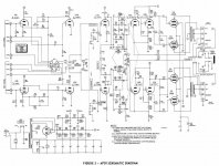
I have an ancient Bogen AP-35 i acquired and one of the output tubes was fried. It uses 7408's 2 in push pull. I replaced them all with 6V6GT's and the sound now is much softer volume wise and has much less power. Also from about 3/4 to full volume, the sound becomes VERY distorted. Could this be a biasing problem? If so the unit has no bias adjustments that I can see. Should i insert a resistor and a pot in between the 2 tubes for bias that way? If so how would i find what values to use. Also the filaments for the 12ax7's in the phono stage do not work. I think this is somehow connected as the power supply that feeds the cathodes of the power tubes are also used to power the filaments. Very weird setup with this. Also in the schematic, the 2 12ax7's that aren't in the phono section are actuall 6eu7's in the unit. Not sure why.
Also is there any ways of improving the sound?
Any ideas are welcome. Thanks.
Also is there any ways of improving the sound?
Any ideas are welcome. Thanks.
Another thing.
Since the output tubes derive their operating bias through the filaments of the 12AX7 tubes, a short within one of the output tubes which causes the tubes to draw more current is likely to burn out the filaments of the 12AX7's and possibly cause the electrolytic capacitor to fail.
Not a good design.
Well, I took a closer look at it's guts and realized whoever had it before me changed the resistors in the power supply and had many wrong values. Also the electrolytic capacitor in the bias circuit was done (probably original) so I replaced all the resistors in the power supply, replaced the bias cap and put a fresh pair of 12ax7's in the phono section and BLAMO! SUCCESS!
Thanks Frank, I appreciate the knowledge.
Thanks Frank, I appreciate the knowledge.
I would pull V1 and V2 and use a proper cathode resistor for the op tubes. You probably don't need the phono section. Try using the "tape out" RCA jacks to insert your CD player inputs to bypass all those old switches. Ultimately, you could probably connect the RCA jacks directly to the grids of V4. That will do away with the tone controls and provide a much cleaner signal.
Last edited:
Yes, use one cathode resistor per pair. I would start with 300 ohms to be safe. Measure the plate voltage and the combined screen and plate currents and ensure that the max dissipation is 14W max. Your plate voltage is almost 350V according to the schematic (this violates the max plate voltage!), so you want no more than 80mA through the cathode resistor for 24V at the cathode of the op tubes. If 300 ohms results in an acceptable dissipation, then you can try 250 ohms.
Once you get it running correctly, try connecting the input to a stereo 100k pot and the wipers to the grids of V4 to hear if you like it better than through the tone controls.
Once you get it running correctly, try connecting the input to a stereo 100k pot and the wipers to the grids of V4 to hear if you like it better than through the tone controls.
Last edited:
Hi I measured with the 12AX7 bias -- dc V
Rect 364 --- plates 356 - screens 328 - cathodes 20
with separate 300 ohm unbypassed resistors I get rect354 - plate 348 - screen 326 - cathode 20v all good ? 100mf bypass caps ? thanks again -- am I in the safe poreating range for the 7408s ?
Rect 364 --- plates 356 - screens 328 - cathodes 20
with separate 300 ohm unbypassed resistors I get rect354 - plate 348 - screen 326 - cathode 20v all good ? 100mf bypass caps ? thanks again -- am I in the safe poreating range for the 7408s ?
- Status
- This old topic is closed. If you want to reopen this topic, contact a moderator using the "Report Post" button.
- Home
- Amplifiers
- Tubes / Valves
- Bogen AP35 amp problem