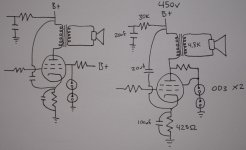
I have been doing some reading about possible tweeks to my KT-88 amp. I was thinking of trying a VR tube regulated screen. Here are two sketches. Would one of these work better then the other? I was thinking of 2 0D3's for 300v or and 0C3 and an 0D3 for 255v.
I was thinking also of using a resistor and a pot so I could play with different VR tubes.
I was thinking also of using a resistor and a pot so I could play with different VR tubes.
Attachments
Lots of useful information in this thread.
RCA Voltage Regulator:
http://www.diyaudio.com/forums/showthread.php?s=&threadid=129357
Enjoy,
RCA Voltage Regulator:
http://www.diyaudio.com/forums/showthread.php?s=&threadid=129357
Enjoy,
Thanks for the link.
Those regulators are cool. There were a few other threads I checked out, including one were fdegrove posted a VR screen supply for an 807 (which is the basis for what I drew). One thing I'm wondering is whether or not it would be worth implementing as shown. How great would the return be by going with something more complex than 2 VR tubes?
Those regulators are cool. There were a few other threads I checked out, including one were fdegrove posted a VR screen supply for an 807 (which is the basis for what I drew). One thing I'm wondering is whether or not it would be worth implementing as shown. How great would the return be by going with something more complex than 2 VR tubes?
Both will not work because VR tubes can't survive currents needed to regulate KT88 grids directly. I even don't speak of the 2'nd version where VRs are powered from anode....
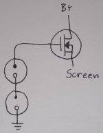
Take one cheap MOSFET and use it as a source follower with your VR tubes to get more than plenty of regulation.
Take one cheap MOSFET and use it as a source follower with your VR tubes to get more than plenty of regulation.
Ahhh, I was under the impression from my reading of other threads that the screens drew about 5ma idle and around 15 when pushed. Where can I find info on the current draw of screens?
I also read that when you set up a VR regulator that you allow for enough current to supply the load + the midpoint of the VR tubes rated max. So if you ran your tube at 80ma and wanted the VR tube at 20ma, you set up your psu to deliver 100ma at the desired voltage, the tubes would draw their 80ma and the 20ma would go to the VR tubes. I'll try and find the post where this is outlined by someone smarter than myself...
I also read that when you set up a VR regulator that you allow for enough current to supply the load + the midpoint of the VR tubes rated max. So if you ran your tube at 80ma and wanted the VR tube at 20ma, you set up your psu to deliver 100ma at the desired voltage, the tubes would draw their 80ma and the 20ma would go to the VR tubes. I'll try and find the post where this is outlined by someone smarter than myself...

Doing more research. The Kt-88 spec sheet states that the max screen dissipation is 8w, if I put that and 300v into a Ohms law calculator it comes out to 26.67ma, which is right in the middle of an 0D3's operating range right? So anything under that Max screen rating should be ok.
athos56 said:Doing more research. The Kt-88 spec sheet states that the max screen dissipation is 8w, if I put that and 300v into a Ohms law calculator it comes out to 26.67ma, which is right in the middle of an 0D3's operating range right? So anything under that Max screen rating should be ok.
It is up to you, but speaking of audio I would always think of dynamics, keeping in mind clipping that happens in real life for sure. I would check how it sounds with and without a source follower before drawing a final conclusion.
Right, I'm not trying to argue ") , I'm trying to make sense of what I see and read. What operating point should you run a KT-88 screen at? What voltage and how much current will it draw? I mean I could always just hook up the UL tap and call it good, but I thought a little regulated supply would be fun to try.
, I'm trying to make sense of what I see and read. What operating point should you run a KT-88 screen at? What voltage and how much current will it draw? I mean I could always just hook up the UL tap and call it good, but I thought a little regulated supply would be fun to try.
, I'm trying to make sense of what I see and read. What operating point should you run a KT-88 screen at? What voltage and how much current will it draw? I mean I could always just hook up the UL tap and call it good, but I thought a little regulated supply would be fun to try.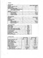
athos56 said:Right, I'm not trying to argue
I use screen voltage regulation in 3 models of my amps, both for 6L6 and GU-50. Also, I sense screen grid currents to control optical compressors. Voltage regulators are designed to supply more of current they want, while sensors are fine tuned by trimpots to start compression as soon as screen grid currents start going up sharply.
6L6 grids I run at 305V with 400V on anodes, while GU-50 screen grids I run at 275V when anode voltage is 800V. Biasing tubes I monitor cathode currents in order to set working points. Screen grid currents at idle don't matter as soon as tubes are alive.
athos56 said:From the looks of the spec sheet, under typical operation at 225v the draw is 5ma at idle. This is why I'm confused. Is there a lot of clipping in this typical application?
Is there a lot of clipping, depends on conditions you are going to use your amp in: desired sound pressure, room conditions, sensitivity of speakers, max power of your amp.
Cool, I guess I was just pointing out that if the current is 5ma at idle and with the max dissipation of 8w, at the voltage I was looking at the current was 26ma. It seems like the VR tubes could handle whatever happened current wise. I'm not understanding where the clipping and blown VR tubes are coming from. But I admit I am an amature with only 4 amps completed. There is always the UL taps on my OPT if I can't figure it out.
Approaching clipping pentodes start drawing more current so if your regulator can't supply it screen grid voltages drop down abruptly that may cause different character of distortions you (or users of your amps) may not like.
Edit: VR tubes can't draw "whatever current"! And they have non-zero dynamic resistance, so a source follower keep them happy all the time: regulation depends on dynamic resistance of what supplies/draws the current VS their own dynamic resistance.
Edit: VR tubes can't draw "whatever current"! And they have non-zero dynamic resistance, so a source follower keep them happy all the time: regulation depends on dynamic resistance of what supplies/draws the current VS their own dynamic resistance.
Ok, I'm not against a source follower, I just have to look up how to hook it up. Thanks for the replies.
Here is the page where I got the Idea, I wanted to do something similar.
Post on 807 VR screen regulator
Here is the page where I got the Idea, I wanted to do something similar.
Post on 807 VR screen regulator
Re: A start...
Yes. You will need to supply current to your VR tubes of course, also a gate stopper and screen grid stoppers will be needed to avoid HF oscillations. I would start with 1K each gradually decreasing screen grid stoppers.
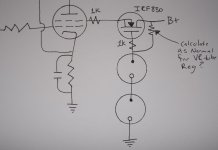
athos56 said:Ok here is a literal translation of the post linked above, I'm going to assume that its missing something. Is this close?
Yes. You will need to supply current to your VR tubes of course, also a gate stopper and screen grid stoppers will be needed to avoid HF oscillations. I would start with 1K each gradually decreasing screen grid stoppers.
- Status
- This old topic is closed. If you want to reopen this topic, contact a moderator using the "Report Post" button.
- Home
- Amplifiers
- Tubes / Valves
- Question about a VR screen supply