Hi Everyone,
I have no doubt I am making some basic mistake but I am struggling to work out what is going on
I am in the building stage of an 845 amp and I have just completed the bias power supply.
I have tested it without any load.
Bench test at 20v, all OK with appropriate bias voltages for low input voltage.
Bench test at 200v. Perfect, with bias voltages within tolerances and appropriately adjustable but both resistor networks (but especially the bridge between the positive poles of the duel cap) becoming unacceptably (as in will burn out) hot within about 30 seconds.
I have triple checked my wiring, all OK as far as I can see. Furthermore, apart from the heat, the supply works perfectly.
The resistors are all of appropriate value and power rating. I measured the current in the circuit at 100mA - too many watts to dissipate!
Does anyone know what is going on? Obviously, I am measuring the supply in isolation and unloaded but I would have thought that any load would increase the current through the resistor network and make things worse?
I am sure I have made some fundamental error, can anyone help?
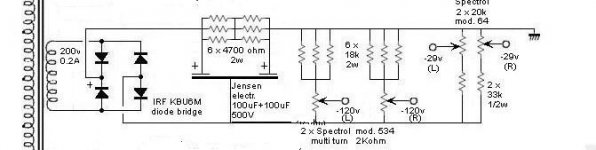
I have attached the bias supply schematic and link to the whole schematic.
Cheers,
Rob
http://www.audiodesignguide.com/New845/New845v2.html
I have no doubt I am making some basic mistake but I am struggling to work out what is going on
I am in the building stage of an 845 amp and I have just completed the bias power supply.
I have tested it without any load.
Bench test at 20v, all OK with appropriate bias voltages for low input voltage.
Bench test at 200v. Perfect, with bias voltages within tolerances and appropriately adjustable but both resistor networks (but especially the bridge between the positive poles of the duel cap) becoming unacceptably (as in will burn out) hot within about 30 seconds.
I have triple checked my wiring, all OK as far as I can see. Furthermore, apart from the heat, the supply works perfectly.
The resistors are all of appropriate value and power rating. I measured the current in the circuit at 100mA - too many watts to dissipate!
Does anyone know what is going on? Obviously, I am measuring the supply in isolation and unloaded but I would have thought that any load would increase the current through the resistor network and make things worse?
I am sure I have made some fundamental error, can anyone help?
I have attached the bias supply schematic and link to the whole schematic.
Cheers,
Rob
http://www.audiodesignguide.com/New845/New845v2.html
Attachments
Hi Rob,
I think you have basically discovered the answer on your own. Too much power is being dissipated (wasted) through the resistor network. Simple ohms law (I=E÷R and P=IE) will tell you this. For the values given with an estimated assumed voltage of 250V (200V X 1.41 loaded) you're dissipating over 15 watts quiescently. This puts the combined resistor wattage at or below this level, which is simply not enough. Resistors should always be chosen for two or three times (or more) their actual operating wattage.
I don't know what the author was thinking, but IMO his numbers are poorly chosen. Why run such a high quiescent current? If it is to help with regulation, I would use a 25 or 50 watt bleeder at the output of the supply. And 20mA would be sufficient, not 60 or more. Then I would increase the value of the bias pots and their series resistors so as to reduce their operating dissipation. Multi turn controls are expensive and do burn out from excessive current flow and heat.
If the intent was to provide a low impedance DC source to the 845 grids, this is all well and good. But the source does not have to be this low. I've tested enought 845s to know that a properly operating tube will only draw quiescent grid current in the microamp range. And operating at power this will increase somewhat, but never to a milliamp unless the tube is very gassy.
Victor
Thanks Victor,
That's what I thought (in fact I thought that it was more like 30W when I measured current draw through the resistor bridge) and what you say makes perfect sense.
This is what I don't understand - The author of the circuit, Andrea Ciuffoli has made several versions of this amplifier. Other members of the forum have written to me and said they have built this design. No one has reported any problems. Am I the first person to notice that the bias resistors burn out within a couple of minutes???
I would love Andrea to comment but I am not sure how to identify this thread to him? I am wondering whether or not he has transcribed the schematic correctly but in looking at the photo's of his design the resistors seems to be of the stated values.
In any case, the problem seems to exist. I have my multiturn pots now and they were expensive! Is there a simpler way to modify this circuit without replacing the pots and resistors?
Rob
Rob11966 said:Is there a simpler way to modify this circuit without replacing the pots and resistors?
Sorry, not that I can think of. I went and looked at all the pictures too of the supplies. The three 18K resistors in parallel (6 total) look more like 1600 ohms to me based on the colors I see. Perhaps his camera or my monitor. Never the less, ohms law doesn't lie. If you have 100 mA of current flowing in the bias supply, that's crazy. All I can think of is a leaky filter cap or more then 200V AC going in.
Hi again Victor,
I have redone my calculations and on second review, I think the schematic is OK.
According to what I have worked out, theoretically the whole circuit (as tested, without any bias load) should draw 40mA. If we just look at the 4700 resistor bridge this would equate to approximately 5W accross the network or about 0.83 W/resistor which should be fine.
However they are getting hot and I have measured the current draw at over 100mA.
If my above calculations are correct then in real life I must have a problem with the circuit - which is odd as the voltages are OK. I will quadrouple check.
Aleaky cap may explain the situation but I would also be reasurred if you could have a look at my theoretical calcs to see if I am correct concerning the current draw and power dissipation. My first calcs were based on the measured current draw (100mA) rather than the calculated (40mA)
Cheers,
Rob
Hi Victor,
It is a Jensen duel cap. I will measure the voltages tonight. They should be around 280v I would guess.
I am thinking leaky cap. A current leak through the capacitor would explain the problem. I might substitute a different cap to see if it makes a difference.
As far as the resistors go, I must admit, because they were new, I only tested one in each pack.
Do you have any comment on my theoretical calcs for current draw? It would reassure me to see that the schematic was OK in principle - I could then be much more certain that I was dealing with a faulty component or incorrect hookup.
Thanks for helping,
Rob
Rob..
I came up with..
14.87694122 Watts total
52.886388 mA
5318.94889 Ohms total
Whats the voltage divider for the second terminal for??
Yeah I would up the values with some Five or ten watt wirewounds for the PWR resistors to keep them operating relatively cool..don't want any thermal variations to foul things up.
Check your 'Q' with the inductance of wirewounds tho' ...don't want to make a 'tank' circuit on accident.
_____________________________________________Rick........
Attachments
Hi Richard,
I come up with a slightly different number for the second resistor group (which I have labelled R2).
You came up with 2185 and I have come up with 3475. I could be wrong but I can't see where? Please correct me if you come up with your figures again.
If you use 3475 (and as I mentioned I could be wrong), then you get a total R of 6608 with a current of 42mA and a total power 11.65W Total.
The combined power ratings of the resistors are 24W and on the face of it this would seem to be OK.
So, I am getting happier that the schematic is probably OK but my made up circuit is not. I take your point regarding the wirewounds and this may be a good idea but I am measuring over 100mA in the circuit which implies a current draw not identified on the schematic. Even 5W wirewounds won't cope with this sort of current.
With respect to your question concerning the voltage devider, I think that it is just a way of arranging commonly available resistors to get the total resistance and power rating required?
I will measure voltages accross both sides of the duel cap tonight and post results. I will also check the current flow through the capacitor, this may give some more information.
I think that a possible explanation for the difference between calculated (42mA) and measured (>100mA) is most likely to be explained by a faulty cap with a current leak through it. I will replace the capacitor and see if it makes a difference. I hope it's not the cap however. It is new, from denmak and expensive!!
Thanks for the help so far, the problem is slowly becoming clearer.
Cheers,
Rob
Attachments
OK,
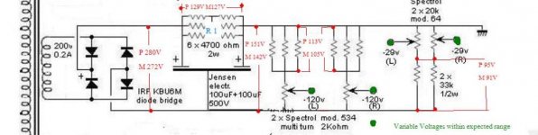
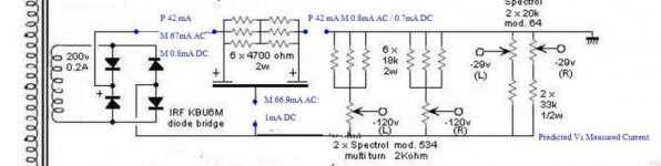
I have attached a couple of schematics. The first is predicted voltage vs actual measured voltage. You can see that the voltages are all spot on. So far no problems except the resistors are still getting damn hot.
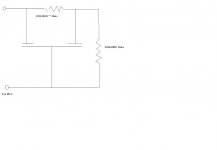
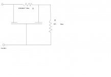
The second schematic (attached in next post) is predicted current vs measured current. I broke the circuit and placed my digital fluke in series as indicated in the schematic. Here is where I got some odd readings and I think that it must be measurement error. Prior to the first stage of the smoothing cap I measured 67mA AC with no almost no DC (predicted 42mA). I measured very similar readings on the negative side of the cap. Current was negligible on the other positive side of the cap - I would have expected 42mA here.
This is confusing me. The voltages are spot on and the circuit works fine (apart from the hot resistors) but the current measurements are odd. As I don't often measure current, I can only assume that I am measuring incorrectly?
If the current measurements can be explained by user (me) error then I think that I will have to accept that the circuit has been built correctly and I will just have to up the power ratings of the resistors. Perhaps I am just overly worried about the temperature and perhaps the heat is within tolerance, however they are hot enough to burn when touched.
Just a couple of quick points. I changed the cap and found same measured results. I checked all of the resistor values and ratings. I had a look at the voltage with my scope and it is well smoothed at 272V with no ripple.
So after all that waffle, here are my questions -
1. How are the odd current readings explained in the presence of voltages which measure as expected?
2. How hot is too hot - obviously a fire is not good but how hot do 2W power resistors get?
Once again, thanks for sticking with me. I am learning and it was quite satisfying to work out all of my voltages and find them measured as predicted.
Cheers,
Rob
I have attached a couple of schematics. The first is predicted voltage vs actual measured voltage. You can see that the voltages are all spot on. So far no problems except the resistors are still getting damn hot.
The second schematic (attached in next post) is predicted current vs measured current. I broke the circuit and placed my digital fluke in series as indicated in the schematic. Here is where I got some odd readings and I think that it must be measurement error. Prior to the first stage of the smoothing cap I measured 67mA AC with no almost no DC (predicted 42mA). I measured very similar readings on the negative side of the cap. Current was negligible on the other positive side of the cap - I would have expected 42mA here.
This is confusing me. The voltages are spot on and the circuit works fine (apart from the hot resistors) but the current measurements are odd. As I don't often measure current, I can only assume that I am measuring incorrectly?
If the current measurements can be explained by user (me) error then I think that I will have to accept that the circuit has been built correctly and I will just have to up the power ratings of the resistors. Perhaps I am just overly worried about the temperature and perhaps the heat is within tolerance, however they are hot enough to burn when touched.
Just a couple of quick points. I changed the cap and found same measured results. I checked all of the resistor values and ratings. I had a look at the voltage with my scope and it is well smoothed at 272V with no ripple.
So after all that waffle, here are my questions -
1. How are the odd current readings explained in the presence of voltages which measure as expected?
2. How hot is too hot - obviously a fire is not good but how hot do 2W power resistors get?
Once again, thanks for sticking with me. I am learning and it was quite satisfying to work out all of my voltages and find them measured as predicted.
Cheers,
Rob
Attachments
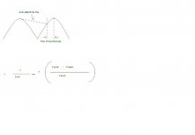
Maybe the cause of your weird readings are the result of the conduction angles ...your ripple no matter how small...that might explain the high AC current going into the first terminal of the cap..and the low DC current.
If your not familiar with this...The time which the PS can recharge the cap is very small & shoots out short duration high current pulses to recharge the cap. The current "averages" out to a much lower figure.
____________________________________Rick.......
If your not familiar with this...The time which the PS can recharge the cap is very small & shoots out short duration high current pulses to recharge the cap. The current "averages" out to a much lower figure.
____________________________________Rick.......
Attachments
I'm just thinking measurements with you equipment cannot cope with the dynamics involved with rectification...In the 'middle' of..
Your resistors really shouldn't be 'hot' to the touch, this invites thermal breakdown over time. While it probably works OK in the ideal world..what happens when your amp gets left on accidently (24+Hrs )
and its' 109 F, you "accidently" left you 'cabinets' closed (No air circulation) et. al.
I would shoot for 'warm' to the touch.
Perhaps I'm paranoid or some such but I think a big dose of overengineering is called for here, besides....we all are "wasting" power on these "dinosaurs" eating up hundreds of watts for a paltry few watts of audio power....but it's the glowing glass things we all appreciate anyways.
________________________________________Rick............
Hi Richard,
I am sure that you are correct about the AC ripple. I don't fully understand it as my scope shows a fully smoothed DC voltage at all points but there is no doubt that before the first cap connection I am only measuring AC current and no DC (presumably because the current is swinging back and forth through zero). Post capacitor, I am measuring only DC and not AC.
I have solved the problem with respect to the issue about higher than calculated current flows. There is a significant amount of current flowing through the capacitor - contributing to the overall current (70mA) which does not seem to change m even when the circuit is loaded.
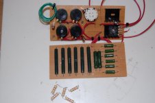
As the circuit works perfectly, I have resolved the issue by uping my resistor power ratings. I now have over 100W of power capacity and it works well.
Thanks for the help. If some one is able to outline what is going on with the capacitor, then I will consider it 'case closed'.
I have attached a picture of the new board with the old 2W resistors for comparison.
Cheers,
Rob
I am sure that you are correct about the AC ripple. I don't fully understand it as my scope shows a fully smoothed DC voltage at all points but there is no doubt that before the first cap connection I am only measuring AC current and no DC (presumably because the current is swinging back and forth through zero). Post capacitor, I am measuring only DC and not AC.
I have solved the problem with respect to the issue about higher than calculated current flows. There is a significant amount of current flowing through the capacitor - contributing to the overall current (70mA) which does not seem to change m even when the circuit is loaded.
As the circuit works perfectly, I have resolved the issue by uping my resistor power ratings. I now have over 100W of power capacity and it works well.
Thanks for the help. If some one is able to outline what is going on with the capacitor, then I will consider it 'case closed'.
I have attached a picture of the new board with the old 2W resistors for comparison.
Cheers,
Rob
Attachments
Hot is a relative term. Most resistors can tolerate a good bit of heat. If they are operating at, say, 50 degrees C, they will be too hot to hold your finger on, but it won't faze them. That said, there is no problem running higher rated parts. Total heat generated with be the same, just spread over more area.
One suggestion; Mount your resistors so that they are 1/2 cm or so off the perf board to improve air circulation around the part.
Sheldon
One suggestion; Mount your resistors so that they are 1/2 cm or so off the perf board to improve air circulation around the part.
Sheldon
Hi Sheldon,
I was actually going to mount them as you described but I figured that they were so overrated that it didn't really matter. However, good practice is good practice and I will mount all future power resistors as described. I would redo the board but I am out of resistors and the leads are now too short to use the old ones
Thanks for the advice.
Rob
Richard Ellis said:
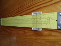
Yep...Did the math wrong..How about 3475.420091!!________________________________________Rick............
Back to one of these. The beauty is you can ignore all after the point and you won't make the same mistake !!
richy
Attachments
- Status
- This old topic is closed. If you want to reopen this topic, contact a moderator using the "Report Post" button.
- Home
- Amplifiers
- Tubes / Valves
- Help needed with bias circuit