hi there
i need help on trying out dc heater supply for 6.3vdc 1.5A for the preamp i am running.
what kind of regulator to use? or use direct from rectifier and drop the voltage with the resistor to the required voltage?
it does need to float 25vdc above ground. where do i connect this floating connection?
to the ground of the heater supply or to the power transformer CT?
thanks in adv for the help
erwin
Erwin..We really do need a schematic so we can see what we all are working with.
For regulated DC for filiments, the 317 series regulators will do nicely....easy to configure, very clean DC.
As to the "floating 25 V"...I don't understand...nor where you need to connect to. This is where we need a schematic....
______________________________________Rick............
For regulated DC for filiments, the 317 series regulators will do nicely....easy to configure, very clean DC.
As to the "floating 25 V"...I don't understand...nor where you need to connect to. This is where we need a schematic....
______________________________________Rick............
Hi Rick
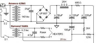
here is the attached psu schematic.the floating is set by the 26K and 121K resistors. which five a nice 25vdc floating from ground to the heater supply. this floating dc is claimed can extend the life of the tube. since its not a problem then i just wired as suggested.
lm317... sounds good... will try this.
but will the floating dc affect the lm317 or the heater PT ?
erwin
Attachments
Yo Erwin,
A DC filament supply can be either regulated or unregulated. Regulated is better and requires less total parts for a quite DC output. However, if you need to elevate it 25 volts for heater/cathode reasons, you must keep it totally floating above ground or your supplys will be in conflict. Connect the 25 volts to the output of the DC supply were the filaments connect. Never before the regulator or rectifiers.
No, you cannot rectify 5 volts and expect to get 6 volts out under load. You must start with a higher voltage AC of at least 10 volts. This is because under load the voltage will drop down. And if you use a series pass device like a 317, you need at least a few volts extra so the device will see a differential which it need to operate. Capeesh?
Yo HollowState
thanks for the help. nice.
will hook one up and post back. i will just follow the 7v rules for the regulated supply. hence input of 15vdc and regulate it to 6.2vdc.
one more question. if the required 1A for AC current supply. is it still need 1A for DC current supply? or in DC it needs more?
i ask this question as i have try a chip regulated dc supply. though this psu rated for 3A. the 2n3055 runs extremely hot that i cant touch the heatsink (heatsink already double the required size). also the transformer runs very hot to touch that i have to disconnect them after less than an hour
erwin
milen007 said:one more question. if the required 1A for AC current supply. is it still need 1A for DC current supply? or in DC it needs more?
If you are asking if the tubes need more current under DC power, the answer is no, they require the same as for AC.
If things are running that hot, you are dissipating a lot of power. If your wiring is correct, then you need more heat sink still. And I just noticed something in your posted schematic. You show a capacitor across the filament winding. Don't do that! A capacitor represents a load across AC. This will strain and overheat your transformer. And you don't need one across the HV either.
HollowState said:
If things are running that hot, you are dissipating a lot of power. If your wiring is correct, then you need more heat sink still. And I just noticed something in your posted schematic. You show a capacitor across the filament winding. Don't do that! A capacitor represents a load across AC. This will strain and overheat your transformer. And you don't need one across the HV either.
Yo HollowState
superb. will take that 4.7uf out and see what happen.
whats the reason why have to take out the 4.7uF caps before the filament in my case?
another questions, for regulated psu, can we put capacitor after the regulator? as i saw some people use caps after the regulator. is this the one cause the overheating of the PT?

TIA
erwin
milen007 said:whats the reason why have to take out the 4.7uF caps before the filament in my case?
another questions, for regulated psu, can we put capacitor after the regulator? as i saw some people use caps after the regulator. is this the one cause the overheating of the PT?
Capacitors pass AC. It represents a resistor when connected to AC voltage. That's how it is shown on your diagram. There are no rectifiers so there is no DC to filter.
Normally there is a large capacitor before the regulator. After the regulator use only a small value capacitor to quite any possible noise if needed.
(I'm turning in for the night)
Victor
Hi, milen007!
For what purpose it is necessary for you to DC supply for filaments of tubes? Your preamplifier has tubes with direct heating?
If is not present, then your first scheme will unconditionally clean an AC hum from heating of tubes.
In any case, at DC supply of filament of tubes to associate ~ +25V it is possible to any wire of a feed of filament (only for one!)
BW, VU
Vlauga said:Hi, milen007!
In any case, at DC supply of filament of tubes to associate ~ +25V it is possible to any wire of a feed of filament (only for one!)
BW, VU
hi Vlauga
mind elaborate the point above?
nope, its 6t4. no need direct heating. i know i make my own life harder.
reason i try dc is that my locally custom PT for my preamp is of low quality. no problem with voltage on B+. but when it come to filament supply. while drawing only 2A it drop to 5.6VAC. which i think is no good. as my preamp got hum... it sounds like the mobile phone that near the speaker but constant and its audible at almost 2 feet away. i hope that this dc with correct voltage would cure this.
off the shelf trafo is nowhere i can find that supply 6.3v. with dc supply by using off the shelf PT, say 30ct or less, i can manage to get the desired voltage which is 6.2vdc and i have this dc psu laying around.. the one with lm317..
secondly i would like to know if dc supply give better sound. i am in the leaning stage as this is my first diy tube preamp.
any suggestions really appreciated.
another question.
so how could that capacitor of only 4.7uF on the regulated dc psu can cause the PT to operate hot? as i saw schematic from lm317 datasheet has capacitors on psu output?
any link that i can read more about this? thx in adv
erwin
In case of hot PT at you two alternatives of a problem.
1. The discarded transformer. Disconnect it from current of users. Switch it on in AC. If through hour work he remains cold, it is necessary go to the second point.
2. Total quantity of a consumed current filaments of tubes of your amplifier. Compare to passport value of current of the secondary winding of the transformer (1.2A). The first value should be less or equally second.
Inform, what from these points there is a true?
In any case, иcпользование such transformer in similar requirements it is intolerable. Under certain conditions it can fail with critical effect.
BW, VU
P.S. Yes. The main thing to tell has forgotten!
Under your scheme. It is necessary for you to expel R drop and the capacitor 4.7u in case you use an AC for filament supply.
Rdrop it is necessary for you only in case the secondary winding voltage above (on 5 %) 6.3 V at the connected filaments of tubes.
It appears the posted PS schematic one of Poindexter's; you could ask him why the caps are there, as I am kind of wondering myself.
I am also just finishing a breadboard for his music machine and that schematic also shows a 4.7u across the filament secondaries and a .01 across the transformer secondaries. I would guess it's for noise suppression but I'm no expert.
If your filament voltage is too low, you certainly do not need the Rdrop.
Vlauga said:In case of hot PT at you two alternatives of a problem.
1. The discarded transformer. Disconnect it from current of users. Switch it on in AC. If through hour work he remains cold, it is necessary go to the second point.
2. Total quantity of a consumed current filaments of tubes of your amplifier. Compare to passport value of current of the secondary winding of the transformer (1.2A). The first value should be less or equally second.
Inform, what from these points there is a true?
In any case, 8c?>;L7>20=85 such transformer in similar requirements it is intolerable. Under certain conditions it can fail with critical effect.
BW, VU
P.S. Yes. The main thing to tell has forgotten!
Under your scheme. It is necessary for you to expel R drop and the capacitor 4.7u in case you use an AC for filament supply.
Rdrop it is necessary for you only in case the secondary winding voltage above (on 5 %) 6.3 V at the connected filaments of tubes.
hi Vlauga
i have use this psu that rated 3A to power ta2024(if i am not mistaken draw 400mA idle or normal working and 3A peak) and they are working nicely. just a tad of warm. can be consider not even warm only few degree above room temperature.
the PT is rated 3A as well. which worse case would be able to deliver 2A. its quite big and heavy.
"In any case, 8c?>;L7>20=85 such transformer in similar requirements it is intolerable. Under certain conditions it can fail with critical effect." what does this mean?
i do not use Rdrop when i ac powering. only the cap of 4.7uF. and they drop to 5.6VAC when load around 2A (tube rectifier and 4 pcs 6t4 filament).
when i try this regulated psu thats rated for 3A. i only try it on the 4pcs 6t4 filaments. which i estimated 1A or max 1.2A. hence its confusing that the PT and the 2n3055 are very hot and untouchable.
Vlauga said:Yes... Hammond 166K6 (115V/60Hz) - Indonesia AC 50Hz/220V = ?
Your solution?
i do not use hammond 166K6. i custom wound locally my PT to get the right secondary voltage. yep. indonesia ac 50Hz/220v.
boywonder said:It appears the posted PS schematic one of Poindexter's; you could ask him why the caps are there, as I am kind of wondering myself.
I am also just finishing a breadboard for his music machine and that schematic also shows a 4.7u across the filament secondaries and a .01 across the transformer secondaries. I would guess it's for noise suppression but I'm no expert.
If your filament voltage is too low, you certainly do not need the Rdrop.
hi boywonder
yes its Poindexter's psu schematic for 6t4. i take part of it as i do not know how to draw schematic.
if i am not mistaken he said the 4.7uF is to improve the heater supply but you better confirm with him bout this. i saw few schematic with caps on secondary AC as well but forget the value.
my filament voltage is too low. hence i do not use the Rdrop at all.
0.01uf on secondary is kinda snubber network and many people use it. its discuss in threat below discussing the right value for certain VA PT.
http://www.diyaudio.com/forums/showthread.php?s=&threadid=128278
help!!! why the PT is hot. will try the recommended lm317 i got in my drawer and report back.
Erwin
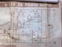
this is the psu schem i use to power the heater 1A. the 2n3055 is getting very hot and the power transfomer become very hot to touch.
TR1=BC177
TR2=BD140
TR3=2n3055
IC=LM723
i float this with 26K and 121k resistor from B+ to the ground of this psu output.
PT is 18v CT 18v and rated 3A.
however, i connect this output to the 4.7uF capacitor from the schematic above. but without the Rdrop resistor.
ps: just quotes the custom transformer for just the heater supply cost 2 or 3 times more from this psu with off the rack PT
TIA
erwin
Attachments
- Status
- This old topic is closed. If you want to reopen this topic, contact a moderator using the "Report Post" button.
- Home
- Amplifiers
- Tubes / Valves
- dc heater supply help