Hi,
I just want to say thanks for the help.
A little background may be in order.
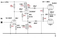
I bought some used Magnavox mono amps , which are the basis of my experiments.I listened to the original schematic/design. I puttered around with it until I came up with this :
http://img101.imageshack.us/img101/...69aarevizj4.png
http://img101.imageshack.us/img101/...upplyforfn4.png
I am NOT saying this is the best, awesome ,the ultimate, or even refined. It is a rough design. I know a little about tubes, am learning as I play, and am thankful they are hardy enough to withstand my abuse.
That being said , I have been running these amps like this for over a year now, with no ill effects. Every time I show someone my current schematic I hear " You're gonna blow up the tubes ." or " You're gonna blow up the PS xfrmr with all that capacitance." When I post some of my ideas I hear " It won't work" or "Everything has been done already, just build an established design".
I tried the single stage PP Triode 6V6 design because it was SO simple, and it seemed to be a reasonable idea. So I proved some people wrong, it DOES work, and found out that it doesn't work to an SPL level that is really usable. Live and learn.
Coldcathode,
Good idea, what are my goals.
I am trying to come up with/find a super simple amp. It doesn't have to be gonzo power , but usable , say 5-10W .
I am trying to reduce parts count and active devices/gain stages. Nothing new here, but I believe less is more. If it is of my design or someone elses isn't really that important , just so it is the most basic and simple of circuits.
As far as my Maggie monoblocks go, I am thinking of using either the 6SL7's I already have, a 6V6 triode tied as a driver , a 6CA4 , or an input tranny . What do you say ?
............................Blake
I just want to say thanks for the help.
A little background may be in order.
I bought some used Magnavox mono amps , which are the basis of my experiments.I listened to the original schematic/design. I puttered around with it until I came up with this :
http://img101.imageshack.us/img101/...69aarevizj4.png
http://img101.imageshack.us/img101/...upplyforfn4.png
I am NOT saying this is the best, awesome ,the ultimate, or even refined. It is a rough design. I know a little about tubes, am learning as I play, and am thankful they are hardy enough to withstand my abuse.
That being said , I have been running these amps like this for over a year now, with no ill effects. Every time I show someone my current schematic I hear " You're gonna blow up the tubes ." or " You're gonna blow up the PS xfrmr with all that capacitance." When I post some of my ideas I hear " It won't work" or "Everything has been done already, just build an established design".
I tried the single stage PP Triode 6V6 design because it was SO simple, and it seemed to be a reasonable idea. So I proved some people wrong, it DOES work, and found out that it doesn't work to an SPL level that is really usable. Live and learn.
Coldcathode,
Good idea, what are my goals.
I am trying to come up with/find a super simple amp. It doesn't have to be gonzo power , but usable , say 5-10W .
I am trying to reduce parts count and active devices/gain stages. Nothing new here, but I believe less is more. If it is of my design or someone elses isn't really that important , just so it is the most basic and simple of circuits.
As far as my Maggie monoblocks go, I am thinking of using either the 6SL7's I already have, a 6V6 triode tied as a driver , a 6CA4 , or an input tranny . What do you say ?
............................Blake
Blake,
Funny we sound a lot alike, see my quote about putting the smoke back in?
That magic smoke can sometimes be real expensive and usually it is the oxidized remains of unobtanium.
I think you are on the right track I am sitting listening to Dianna Krall on mine right now, but it sounds just as good with Metallica, Kenny Wayne Shepard, The Dead, heck the sound is so sweet compared to all the SS stuff I listened to for years that I play music I never really was into just because.
see photos of this amp and an experimental 1625SE (1625 is 807 with 12V filaments) Not enough Umph in the SE 807 needed more gain (only 1/2 12AT7/channel)
see facebook amp album here
I really think you should look at what I posted earlier with the 6SL7's You have em' you have the sockets and looks like all the components try it out
I ran your design on PP Calc and I get LOTS of RED BOXES and unless the gain of the pentode input is better than 20 I don't see how you could be getting more than say 1/2 watt. Since you have pretty efficient speakers it might sound "OK" just quiet.
Which design are you referring to , the single stage (Pentode or Triode) 6V6 or my 2 stage 6V6 triode w/ 6an8 front end ? What is the name of the program you used and where can I get it ?
Can I ask why you want such a high B+ voltage?
I understand that you wind up with a pretty high voltage when you go with the SS rectification but a couple $2 resistors can fix that and with the nice size caps you already have you can make it a LOT quieter than it is and was as far as ripple.
How can I reduce the ripple ?
I looked at your schematic, and have a question. Why do you run the input so that one half of the input tube feeds the other? More gain ? Seems as though a single triode half of a 6SL7 should be plenty of gain. Then again, I don't really know.
I won't have time to work on this until later this week or weekend . By then I'll have decided on a plan of action.
thanks................................Blake
Thanks for your help.
Coldcathode,
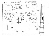
Sorry for hijacking, but I have a similar tubeamp with 6SL7 into a 6L6GC. and would like your opinion. I have only really drawn the front end....I have both 6SL7 and 6SN7 tubes available...the Phase Splitter stage is identical to your previous post...
I have since changed the feedback resistor from 30k to 50k and sounds more warm and to my liking (with 6SL7)...any opinion as to leave it alone or slight mods for the 6SN7? My pre has plenty of gain...also the .05 caps, should I change to .1uf??
The B+ on 6L6 is more around 400 now...I have also indicated the voltages for the 6SN7 (but the second cathode voltage can't be 88v), as when I got the amp, I had both tubes. I believe the 6SL7 is the "correct" tube for this circuit...
Voltage for the 6SN7 are
Plate 1 90V
Plate 2 171V
Cathode 1 2V
Cathode 2 ??? (maybe 2V too)
Voltages for the 6SL7 are
Plate 1 187V
Plate 2 235V
Cathode 1 2V
Cathode 2 2V
Attachments
Which design are you referring to , the single stage (Pentode or Triode) 6V6 or my 2 stage 6V6 triode w/ 6an8 front end ? What is the name of the program you used and where can I get it ?
The design you had with the 6AN8 Pentode Gain/triode inverter to 6V6PP.
I made an assumption that you were feeding this with a CD player. Most CD players are about 500mV RMS or so on the output. As built you are running the 6V6's at 30 volts bias. That means to see the FULL output of the amp you need a Voltage Swing +/- of 60 Volts on the grids of the 6V6's. SO even if the gain of the pentode input was 20 you would only see about 1/3 of the power.
The program I used is the Tube CAD Journal Push Pull Calculator. Costs like $20 to download. It is OK but only does the output stage, had only a few tubes and a few topologies.
I learned a valuable lesson from a TOP NOTCH amp builder and good guy on this forum. Get yourself a copy of a tube manual RCA RC-30 is good. Email me I can get it to you.
You are MUCH better off learning about these things the "old fashioned way" by reading and doing the math.
How can I reduce the ripple ? I looked at your schematic, and have a question. Why do you run the input so that one half of the input tube feeds the other? More gain ? Seems as though a single triode half of a 6SL7 should be plenty of gain. Then again, I don't really know. I won't have time to work on this until later this week or weekend . By then I'll have decided on a plan of action.
Your design assuming an idle current of about 90mA's (can't be sure the numbers on your schematic don't add up well, that's OK but you should get a more accurate Voltmeter) has about 1V or more ripple @ about 100hz.
You have some nice size caps so let's put them to use.
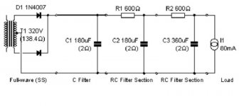
I suggest that we look at a B+ of 300VDC, Bias @ 16V 80mA
So the Cathode resistor S/B 200 Ohms This puts the actual Plate voltage at about 280 with the loss from the DCR of the OPT.
SO we need a B+ of 300VDC and you have about 650 CT AC so coming off the SS rectifier place (1) 180uF Cap to ground then a 600Ohm resistor (10Watt) then (1) 180uF Cap to ground, another 600Ohm resistor and the last 2 180uF caps. You now have about 300VDC with very little if any ripple.
see attachment and wire up one of the PSU's like this. I will work out the rest tomorrow and put up a schema
Attachments
john65b said:Coldcathode,
Sorry for hijacking, but I have a similar tubeamp with 6SL7 into a 6L6GC. and would like your opinion. I have only really drawn the front end....I have both 6SL7 and 6SN7 tubes available...the Phase Splitter stage is identical to your previous post...
I have since changed the feedback resistor from 30k to 50k and sounds more warm and to my liking (with 6SL7)...any opinion as to leave it alone or slight mods for the 6SN7? My pre has plenty of gain...also the .05 caps, should I change to .1uf??
The B+ on 6L6 is more around 400 now...I have also indicated the voltages for the 6SN7 (but the second cathode voltage can't be 88v), as when I got the amp, I had both tubes. I believe the 6SL7 is the "correct" tube for this circuit...
Voltage for the 6SN7 are
Plate 1 90V
Plate 2 171V
Cathode 1 2V
Cathode 2 ??? (maybe 2V too)
Voltages for the 6SL7 are
Plate 1 187V
Plate 2 235V
Cathode 1 2V
Cathode 2 2V
I would set it up for the 6SN7 personally, Not knowing your abilities and what you have available but I might suggest using 6CG7's,(9 pin base) basically they are the same as the 6SN7 but they have an internal screen (pin9) that can be grounded and make for a "quieter" tube.
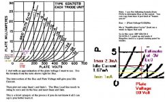
That being said something is wrong with the schematic.
If you bias the first 1/2 @ 2 volts & 90V plate then you need to drop from 258-92=166. According to the chart a 6SN7 draws right about 4mA. So the plate resistor is incorrect, also then the cathode resistor for 2 volts would be 500 ohms.
You say that your preamp has plenty of gain. I will assume it can give us 10V RMS. So we can Bias @ 3V where we draw 1.67mA Idle Current @ 80V to the plates.
So 258-83=175 175 V drop @ 1.67M is about 100K
3V bias @ 1.67M is about a 1K8 resistor.
Output impedance of the stage is ~31.3K
Gain about 13
I would use about a 0.22uF cap to the next stage or else you will roll off the bass too high. (the 0.22 is down 3db @ 23hz, 0.1=51hz and 0.05=102hz) remember this is 6db/octave so it won't be flat response until double the above frequency. Most speakers (at least those I can afford) play down only to about 40hz anyway so the 0.22Uf is good.
Now the second inverter stage 6SN7
Lets say plate voltage of ~100V Bias about 4V @1.5mA Idle Current
258-104=154 154 drop is about a 100K Plate resistor.
Cathode resistor about 2K5 is also good.
Gain = 11.56 Output Impedance is 37.6K so go with 0.25uF coupler
Attached is a quick sketch of the circuit. It may have a couple errors not sure.
It is just something I happened upon one day looking into Williamson type circuits. I am running it very similar with the 6V6's and NO feedback. I do not remember where I saw it but I am very happy with the sound of my amp.
I have not ventured into pentode output circuits yet, but if you google the williamson circuit I think they originally used 6L6's and check my circuit to them. If you want the feedback feed it to the cathode of the input half of the 6SN7 at the socket.
Hope this helps.
Attachments
I'll throw in my $0.02 as well....
A cathodyne phase inverter is the cheap way to go... Dynaco did these for all of their amps... the 6AN8 for the MK-II and MK-III, the 7199 for the MK-IV, Stereo-70 and SCA-35 and the 7247 for the Stereo-35. Easy enough to clone those and eliminate the guess work... chances are highly unlikely you'll better what they achieved with the same tubes in the same topology. In general, I don't like these and would discourage from using one.
A long-tail pair phase inverter is much better, but will require one more triode section for the driver. The 6FQ7 (aka 6CG7) is one of my favorites for phase inverter operation... especially when high voltage swings are required (overkill for the 6V6) with the 5814A for lesser peak-to-peak swings.
Below is a simple and easy to implement LTP inverter that is direct-coupled to the input amp. It also has a simple method to obtain fixed bias from the power transformer (which has no bias tap).
Regards, KM
A cathodyne phase inverter is the cheap way to go... Dynaco did these for all of their amps... the 6AN8 for the MK-II and MK-III, the 7199 for the MK-IV, Stereo-70 and SCA-35 and the 7247 for the Stereo-35. Easy enough to clone those and eliminate the guess work... chances are highly unlikely you'll better what they achieved with the same tubes in the same topology. In general, I don't like these and would discourage from using one.
A long-tail pair phase inverter is much better, but will require one more triode section for the driver. The 6FQ7 (aka 6CG7) is one of my favorites for phase inverter operation... especially when high voltage swings are required (overkill for the 6V6) with the 5814A for lesser peak-to-peak swings.
Below is a simple and easy to implement LTP inverter that is direct-coupled to the input amp. It also has a simple method to obtain fixed bias from the power transformer (which has no bias tap).
An externally hosted image should be here but it was not working when we last tested it.
Regards, KM
I learned a valuable lesson from a TOP NOTCH amp builder and good guy on this forum. Get yourself a copy of a tube manual RCA RC-30 is good. Email me I can get it to you.
Blake - John,
The member I referred to in this earlier post is KM, he just posted some info along the lines of my suggestions.
As he said I TOO think the 6FQ7/6CG7 is AWESOME, very similar to the 6SN7. The medium mu triodes are my preference. You can get HIGH GAIN from the AX7's and such BUT they tend to be noisy. They IMHO are more suited to high gain, overdriven blow your eardrums out guitar amps. I liken it to (if your of my generation) the beginning of the Guns & Roses Video "Sweet Child of Mine" where slash flips off the standby and you hear all the hum.
Not that there's anything wrong with that, it has its place.
KM suggested that I read RC-30, it was the best thing anyone has suggested to date. I had just enough knowledge to be "Dangerous" but not enough to be "productive"
After reading only about 2 sections (maybe 60 - 70 pages) and learning to do the math. (High School level algebra at most) I feel confident with doing a little "designing"
One tip I can offer that you will probably come back to at some point if you have not done this yet.
When looking at Plate Curves from tube manuals to find my operating points I find it easiest to "copy & paste" for example,
I have RC-30 in a PDF form. While working on the points for Johns 6SN7s I highlighted the 6SN7 curve and pasted it into a blank BMP in MS "Paint" I then save it to a directory of Plate Curves.
You can then "plot" the points with different color lines and save it when you have reached the optimum config.
Attached is a sample of what the 1st section of the 6SN7 is running.
For the Gain Calc and output inpedance I "Cheat" if I can.
Follow this link and bookmark it. It works quite well and if the tube is there it is accurate.
Triode Calc Sorry its from another forum.
For the HP or LP response you can use this link.
R-C Filter Calc
Good Luck and I hope I was of some help!!
Attachments
Also,
Bear In Mind that you need to mind your Plate Dissipation and the Absolute Imax of the tube from the spec sheet!!
For the triodes in a power stage I use about 70-80 percent of the max plate dissipation and plot that as the idle current and plate voltage.
For instance the Plate Dissipation max for the 6V6 is 14 Watts so
14 X .8 = 11.2 watts
If I want a B+ around 300Volts then 11.2/300=.0373
Plot the 37.3mA and 300V see if the cross near a specific negative grid voltage. If so then adjust them to meet there and that's the bias.
I then check the Bias number to the formula from the previous post and if they are similar +/- 20% I run with it. If not I play around some more.
BTW for Triode in PP use 2 x all the currents and the voltages are the same. The cathode resistor is 1/2 what the single tubes is.
To get an idea of the power output just do the following
Subtract the Imin from the Imax. This is the current swing
Plot the voltage of the Imax & 0V Grid intersection of the load line and call that Vmin.
Plot the voltage of the intersection of Imin and the 2xBias and call that Vmax
Subtract Vmin from Vmax. This is the Voltage Swing.
Then (Voltage Swing x Current Swing) / 8 = Approximate Watts
For PP Double the Current Swing
Also, if you find the impedance of the loadline:
Voltage Swing / Current Swing you should at least double that for OPT impedance. Maybe 2.5 or 3 times for SE
Coldcathode,
Wow. Tons of info. I will make an attempt to get RC30 - any help on where to find would be appreciated (amazon? I assume it is a book/manual like Morgan Jones'?).
One more question - How do you feel about LED Bias? 3V on the 6SN7 cathode would be pretty easy...
Wow. Tons of info. I will make an attempt to get RC30 - any help on where to find would be appreciated (amazon? I assume it is a book/manual like Morgan Jones'?).
One more question - How do you feel about LED Bias? 3V on the 6SN7 cathode would be pretty easy...
Coldcathode - thanks for all the attachments...I really appreciate it.
Before I replace any components, I took one last look at the circuit to identify existing conditions...they are as attached...I also have a plug in SS rectifier that I can swap out the 5R4 existing to get a B+ of 436V and B++ to 300V, but for now let's looks at the 5R4 readings as shown below...
The fist stage is close to what you propose with 3.5V bais. The second stage would require some minor changes to get as you propose...
I have the .22 Film caps ready to drop in too...
Tubecad says around 29 watts/channel for output at 4/8 ohm Still playing with Tubecad, but haven't yet found out what the required input voltage is to adequately drive the 6L6GC pair...
Attachments
Also, got another question..
Isn't the RC high pass the .05 cap and resistor to ground after it (470K)? If so, roll off is 7hz...that 31.3K impedance from previous stage is before the cap...is this not correct?
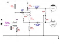
See attached from another schematic...6L6 concertina...this is what I was going to shoot for before stumbling on your post, but planning on an octal equivalent of the 12AX7, that's why I had the 6SL7 (I know a bit short at 70 mu vs 100 mu of the 12AX7)
Maybe I should I type less and read (RC-30) more??
Output impedance of the stage is ~31.3K Gain about 13 I would use about a 0.22uF cap to the next stage or else you will roll off the bass too high. (the 0.22 is down 3db @ 23hz, 0.1=51hz and 0.05=102hz) remember this is 6db/octave so it won't be flat response until double the above frequency. Most speakers (at least those I can afford) play down only to about 40hz anyway so the 0.22Uf is good.
Isn't the RC high pass the .05 cap and resistor to ground after it (470K)? If so, roll off is 7hz...that 31.3K impedance from previous stage is before the cap...is this not correct?
See attached from another schematic...6L6 concertina...this is what I was going to shoot for before stumbling on your post, but planning on an octal equivalent of the 12AX7, that's why I had the 6SL7 (I know a bit short at 70 mu vs 100 mu of the 12AX7)
Maybe I should I type less and read (RC-30) more??
Attachments
john65b said:Coldcathode - thanks for all the attachments...I really appreciate it.
Before I replace any components, I took one last look at the circuit to identify existing conditions...they are as attached...I also have a plug in SS rectifier that I can swap out the 5R4 existing to get a B+ of 436V and B++ to 300V, but for now let's looks at the 5R4 readings as shown below...
The fist stage is close to what you propose with 3.5V bais. The second stage would require some minor changes to get as you propose...
I have the .22 Film caps ready to drop in too...
Tubecad says around 29 watts/channel for output at 4/8 ohm Still playing with Tubecad, but haven't yet found out what the required input voltage is to adequately drive the 6L6GC pair...
John,
You are well on your way. I will look at 6L6 curves myself today (at least up until the Nascar race comes on)
You have 2V Bias on the second 1/2 that should be OK since it is not a gain stage just a Phase Splitter. As a matter of fact I am not sure it even needs Bias. I have seen the circuits with and without Cathode Bias at this stage. I myself need to learn more about this stage.
What we are building here looks like a typical "Williamson" 6L6 I think.
Mike
Isn't the RC high pass the .05 cap and resistor to ground after it (470K)? If so, roll off is 7hz...that 31.3K impedance from previous stage is before the cap...is this not correct?
You are CORRECT ! Sorry I was rushing through the analysis and got RC-CR backwards. The .05's WILL work. Use whatever the best quality cap you have is.
See attached from another schematic...6L6 concertina...this is what I was going to shoot for before stumbling on your post, but planning on an octal equivalent of the 12AX7, that's why I had the 6SL7 (I know a bit short at 70 mu vs 100 mu of the 12AX7)
The GAIN of the 1st 12AX7 stage is 75. Can't really say what you need until I look at 6L6 curves. Pretty low B+ must have to do with possible Screen Voltage limits?
You OPT's do not have UL taps correct?
John,
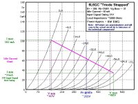
I looked it over and there is an issue. You are using the PP calc and putting in values based on Pentode mode I think. The PP only uses TRIODE mode #'s.
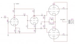
I made some assumptions and came up with this idea.
Use the 250R cathode Resistor as you drew it, and the cap is OK also.
This gives a 31V bias.
Use the B+ of 386 (assuming a 61mA) idle current (check that out against your PSU IDK what you have there.
Tie the Screen Grid to the Plates (Pin 4). Now you are in Triode Mode which yields better distortion #'s.
I am assuming a P-P of the output transformer of 5K.
This should get you about 6 Watts output with low odd order distortion.
You can drive it further into distortion and it will clip at about 19Watts or so.
As you have drawn the input you can reach the 6 or so watts with a signal of ~2.5V RMS. That should be well within the range of you PRE.
You should get about the same sound I am getting which is more than enough for listening with 88/db 1W@1M speakers.
I have not delved into the Pentode PP calcs yet so I would not want to offer any suggestions there but Triode is simpler and cleaner. (just down on power vs Pentode)
Attached is a curve I worked out for you.
I looked it over and there is an issue. You are using the PP calc and putting in values based on Pentode mode I think. The PP only uses TRIODE mode #'s.
I made some assumptions and came up with this idea.
Use the 250R cathode Resistor as you drew it, and the cap is OK also.
This gives a 31V bias.
Use the B+ of 386 (assuming a 61mA) idle current (check that out against your PSU IDK what you have there.
Tie the Screen Grid to the Plates (Pin 4). Now you are in Triode Mode which yields better distortion #'s.
I am assuming a P-P of the output transformer of 5K.
This should get you about 6 Watts output with low odd order distortion.
You can drive it further into distortion and it will clip at about 19Watts or so.
As you have drawn the input you can reach the 6 or so watts with a signal of ~2.5V RMS. That should be well within the range of you PRE.
You should get about the same sound I am getting which is more than enough for listening with 88/db 1W@1M speakers.
I have not delved into the Pentode PP calcs yet so I would not want to offer any suggestions there but Triode is simpler and cleaner. (just down on power vs Pentode)
Attached is a curve I worked out for you.
Attachments
There must be something wrong with your program. . .
Funny thing is, I am using the pentode section of the 6AN8 triode strapped, so it is even less gain then the pentode (which I've read has an amplification factor of 30) .
Using a good voltmeter, I've measured 6+ volts at the speaker terminals , with no audible distortion . This is the exact schematic I listed as using for over a year , driven by a dvd player only, through a passive volume control.
1/2 watt output , I don't think so. Not sure about the +/- 60v swing, but it sure doesn't seem to hold true in this case. . .
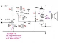
That being said, I appreciate your help, and I plan on trying out your PS schematic . Can I add another RC section to what you listed ? I have qty.5 180ufd caps for each amp.
The tube sockets currently in the amp are octal, besides the driver tube, which is a 9 pin. I was thinking of trying this out before modifying the chassis for all octal sockets.
http://img110.imageshack.us/img110/1044/newampdesign.png
I imagine this would be very sensitive to input , and be very easy to drive. Any thoughts ?
Yeah , I know, it needs a longer tail. Besides that.
Thanks for your help,
....................................Blake
I ran your design on PP Calc and I get LOTS of RED BOXES and unless the gain of the pentode input is better than 20 I don't see how you could be getting more than say 1/2 watt. Since you have pretty efficient speakers it might sound "OK" just quiet.
Which design are you referring to , the single stage (Pentode or Triode) 6V6 or my 2 stage 6V6 triode w/ 6an8 front end ? What is the name of the program you used and where can I get it ?
The design you had with the 6AN8 Pentode Gain/triode inverter to 6V6PP.
I made an assumption that you were feeding this with a CD player. Most CD players are about 500mV RMS or so on the output. As built you are running the 6V6's at 30 volts bias. That means to see the FULL output of the amp you need a Voltage Swing +/- of 60 Volts on the grids of the 6V6's. SO even if the gain of the pentode input was 20 you would only see about 1/3 of the power.
The program I used is the Tube CAD Journal Push Pull Calculator. Costs like $20 to download. It is OK but only does the output stage, had only a few tubes and a few topologies.
Funny thing is, I am using the pentode section of the 6AN8 triode strapped, so it is even less gain then the pentode (which I've read has an amplification factor of 30) .
Using a good voltmeter, I've measured 6+ volts at the speaker terminals , with no audible distortion . This is the exact schematic I listed as using for over a year , driven by a dvd player only, through a passive volume control.
1/2 watt output , I don't think so. Not sure about the +/- 60v swing, but it sure doesn't seem to hold true in this case. . .
That being said, I appreciate your help, and I plan on trying out your PS schematic . Can I add another RC section to what you listed ? I have qty.5 180ufd caps for each amp.
The tube sockets currently in the amp are octal, besides the driver tube, which is a 9 pin. I was thinking of trying this out before modifying the chassis for all octal sockets.
http://img110.imageshack.us/img110/1044/newampdesign.png
I imagine this would be very sensitive to input , and be very easy to drive. Any thoughts ?
Yeah , I know, it needs a longer tail. Besides that.
Thanks for your help,
....................................Blake
Coldcathode -
Actually, the transformer I am using DOES have UL taps. Its a Hammond 1650N...
It is 4300
I will look further into your post later (gotta take care of some stuff....)
BTW - I am attempting to drive my Magnepan MGIIIa (85db/watt) with this amp...sounds OK as it is, but wired in triode mode may be a bit of a stretch on these speakers...
You OPT's do not have UL taps correct?
Actually, the transformer I am using DOES have UL taps. Its a Hammond 1650N...
I am assuming a P-P of the output transformer of 5K.
It is 4300
I will look further into your post later (gotta take care of some stuff....)
BTW - I am attempting to drive my Magnepan MGIIIa (85db/watt) with this amp...sounds OK as it is, but wired in triode mode may be a bit of a stretch on these speakers...
- Status
- This old topic is closed. If you want to reopen this topic, contact a moderator using the "Report Post" button.
- Home
- Amplifiers
- Tubes / Valves
- Tried this out, but needs more gain. . .