Hello, I'm currently designing and building a guitar amp at university and am trying to finalise designing my power amp. It consists of 4 svetlana winged C EL34's in class AB push-pull. My problems begin when considering the maximum anode dissipation of 25W...
I am generally following the push pull design method described by 'The valve wizard' and I have an anode voltage from the supply of 480V and a screen of 467V before any screen resistors. My transformer is a mercury magnetics MMO-100 and supposedly has a nominal primary impedance of 1700ohms. With these specifications I am struggling to see how I can draw load lines on the anode curves I have created on PSpice without going far above the maximum dissipation curve. Does anybody have any ideas how a high anode voltage can be used with EL34's (which doesn't seem particularly uncommon)?
I am generally following the push pull design method described by 'The valve wizard' and I have an anode voltage from the supply of 480V and a screen of 467V before any screen resistors. My transformer is a mercury magnetics MMO-100 and supposedly has a nominal primary impedance of 1700ohms. With these specifications I am struggling to see how I can draw load lines on the anode curves I have created on PSpice without going far above the maximum dissipation curve. Does anybody have any ideas how a high anode voltage can be used with EL34's (which doesn't seem particularly uncommon)?
Some other points I have since noticed - Can the Class B load line be shifted in the same way as the class A line to a chosen quiescent voltage? I suspect not but I can't see any other way to bring it anywhere near a reasonable operating region. Also to get the gradient of the class B line do I still use 1/4 of the transformer primary impedance or do I use 1/8 because I have 4 EL34's?
At the moment my class B line goes through 480V on x-axis and 1.12A on the y-axis which is way too far into the max dissipation region. Is this the correct way of doing things?
At the moment my class B line goes through 480V on x-axis and 1.12A on the y-axis which is way too far into the max dissipation region. Is this the correct way of doing things?
Thanks boywonder, the link you posted is helpful in that it shows me that what I am doing can be done! However, I am still unsure about the points I raised previously of actually how to plot a successful loadline (or 2) on the anode curves. Does anybody have any ideas?
Thanks
Thanks
Ampbuilder:
I am still a tube newbie so my load line abilities are limited.
The links at the bottom of the TDSL page in the above post have lots of vintage tube data, although I did not see any for parallel push pull (PPP).
To clarify, you are running 4 EL34's in a mono, parallel AB push-pull config, correct?
Have you selected an anode load resistor? Are you planning on grid bias or cathode bias? Are you planning on triode, ultralinear, or pentode operation?
Answering these questions may help the experts here help you.
My advice (and this may be totally incorrect) would be to draw your loadline based on your B+, anode load R, for a pair of EL34's based on their connection (pentode, triode, etc) and select your operating point to stay under the max dissipation for the tube. Using two pairs seems to require halving the output transformer impedance, but again, I'm still learning and may be way off base here.
Yes, 4 EL34's in class AB push-pull with 2 pulling and 2 pushing. As far as I know an anode resistor is not required for a power stage because the primary impedance of the output transformer is used instead.
I definitely intend to use pentode operation and probably fixed bias, although I don't think the kind of bias I am using makes much difference to the load curves I'm attempting to draw.
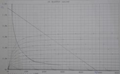
I've attempted to attach a file showing my anode curves (with 1k screen resistor) and my loadline for 1/4 of primary impedance. As you can see, it is very far into the max dissipation region and I can't see how i can rectify this or bias safely at any point along it! This is what made me wonder whether a quiescent point should be chosen which uses the same gradient line but shiftedto a more usable place crossing around 250V and 0.5A.
I definitely intend to use pentode operation and probably fixed bias, although I don't think the kind of bias I am using makes much difference to the load curves I'm attempting to draw.
I've attempted to attach a file showing my anode curves (with 1k screen resistor) and my loadline for 1/4 of primary impedance. As you can see, it is very far into the max dissipation region and I can't see how i can rectify this or bias safely at any point along it! This is what made me wonder whether a quiescent point should be chosen which uses the same gradient line but shiftedto a more usable place crossing around 250V and 0.5A.
- Status
- This old topic is closed. If you want to reopen this topic, contact a moderator using the "Report Post" button.
- Home
- Amplifiers
- Tubes / Valves
- EL34 Power Stage