coldcathode said:BTW does a 45 SE really sound that good? (assuming efficient speakers) I have a couple 45's the only this that "Freaks me out" is the whole heater/cathode thing.
The 45 can be a superb 2-watts... I've designed a few amps with them... the heater is the cathode, not a big deal. Be happy to send you a schematic of one of them... you could also use the input/driver circuit to drive the 829B. It an easily swing 100 volts peak-to-peak.
BTW - calculated the load line on the 829B... load impedance is about 2.8K.
Regards, KM
PS - happy reading... get your calculator out and run the formulas.
The 45 can be a superb 2-watts... I've designed a few amps with them... the heater is the cathode, not a big deal. Be happy to send you a schematic of one of them... you could also use the input/driver circuit to drive the 829B. It an easily swing 100 volts peak-to-peak.
Email me the schematic please.
Thanks for all the help, I have quite a collection of "odd ball" tubes. Anything you might be "looking for"???
They are really taking up a lot of space. Obviously the couple 45's 2A3's etc I want to keep but got a lot of older Pentodes, Triodes etc that I will not be needing.
Don't know if you do any RADIO stuff but I have a whole bunch of 24A's
Update
Well I took in all the information that was suggested by everyone.
I learned a lot in the past week or so (thanks KM!)
Now I THINK I have something workable.
Bear in mind a few things.
1) I am limited to things available in my "junk box" so the OPT's Power Tranny tubes and sockets are what they are.
2) I would love to put chokes in the PS but can't afford it currently.
3) Please check my "math" and excuse any mistakes but I think I checked and re-checked about 4 times.
As drawn I am guessing about 4 watts out?
This is a "temporary" plaything. Sometime I would like to take the 829Bs up to near 42 Watts dissipation B+400V Idle current about 105ma and Bias @ -41. This into a 2K load should be about 15 Watts ?
A few things I am not sure of:
Cin of the 829B's I calc out to about 30pF?
Input = 14.5pF /Pentode
GtoP = .12pF /Pentode
so Gain of ~ 6 x.12=.72+14.5=15.22 *2?
(miller capacitance is a NEW thing to me)
Any thoughts?
Attachments
As I suggested earlier, placing the volume control there is not good. Think about 1/4 to 1/2 volume setting. It raises the source impedance that the 829B will see quite dramatically. It would be better placed in front of the 1st or 2nd stage. Not to mention, the typical CD player puts out 2Vrms. That's 2.8V peak. Your first stage may be able to just barely handle that (it's distortion will be high), but your going to be clipping the crap out of your second stage regardless of volume setting. Also 1M is most likely too large of a grid-leak value for your output stage.
I am actually driving this with the output of a computer sound card. Less than 1V. If I had the luxury of 2.8 volts I would only use a single gain stage and put the control at the input.
As I figure it with about .5V input I get a swing of about 7.5 volts to the second stage. It is biased at about 6V so I adjust the volume down on the PC and prevent the clipping there. Then the second gain stage gets me to about a 32V swing which should be just right for the 829B at about full volume on the POT. I could easily change the value of the pot to something lower like 500K or 100K but that would lower my gain?
The Pot is there in this configuration kind of like a "mute". Most often it will be left at near full pass to the output stage acting mostly like a grid load.
This is a "leftover" thought process from my days in "Car Audio"where you start at the final amplifiers and adjust the signal level back to the source. This allows you to "turn up to 11" on the source volume control without driving anything into clipping or speakers "bottoming out", where the excursion exceeds the xmax of the suspension and the voice coil literally hits the magnet.
Example: I would start with the volume of the head unit at MAX. All the gains on the crossovers and amps at max. Play a track with lots of dynamics and trim back the amp until the power into the drivers was just about maxed out. Then after making note of that setting I would push it up just a notch (about 10%).
I would then adjust the gain on the crossovers down until the I reached the "clean" level. Then reset the Amps to the lower setting. This way at about 80% full on the Source the rest of the system would be at about 80% of full.
If this thought process is flawed let me know. Old habits are hard to break.
This by no means is going to be a low distortion amp. I figure it to be about 9%THD @ 4 watts. It will eventually end up as a "subwoofer" amp where the distortion will be less noticeable.
I more or less wanted to use the new found skills to "design" something on my own. As you can see my original post wouldn't even have played! Since I have all of the components except for about $30 worth of caps and resistors, I can built it and play with it without rousing the "war department", (read WIFE)!
The "ULTIMATE GOAL" is this.
Acquire some nice OPT's with 2.2K Impedance 50W.
New Power Supplies for B+ for each channel 400V @ 250mA ea.
CLCRC filtering on them with nice BIG caps.
Run the 829b's at 400V 105mA Bias of -41V
With a VT preamp and crossover this amp would be a 13W amp for subs about 120hz and down. THD then would be about 11%
I really like the "look" of these tubes. It's like a little glass R2D2 or something. The sockets I have are really cool they are from an old Signal Corps transmitter and the tube sits down inside them. I will put some sort of LED's in the bottom that refract around inside the envelope and "pulse" to the sound level.
Aside from your mention of the Volume control do you see any other "issues" with the circuit?
I would like more sets of "eyes" to look it over before I let the "magic smoke" out!
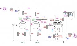
I needed some music in the shop so I built a loose adaptation of this circuit a few weeks ago.

My working curcuit uses SS rectification as it was quick and easy.
OPT is from an old RCA pa amp. The 10 Kohm, 3 Watt resistor is too small so change that accordingly.
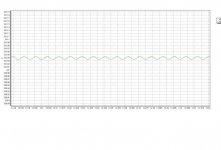
No measurements for you but I can tell you that it sounds fine.
I plan to play with it more this weekend between other projects.
My working curcuit uses SS rectification as it was quick and easy.
OPT is from an old RCA pa amp. The 10 Kohm, 3 Watt resistor is too small so change that accordingly.
No measurements for you but I can tell you that it sounds fine.
I plan to play with it more this weekend between other projects.
I am very happy that i have been successful to connect with you and you in good health. However, keeping same operating point for the 829b from your implementation what should be optimal operating points for the 6n1p-can you please help me here? Sorry for the trouble but I have little idea how to design se circuit using tubes.
Regards
Regards
- Status
- This old topic is closed. If you want to reopen this topic, contact a moderator using the "Report Post" button.
- Home
- Amplifiers
- Tubes / Valves
- 829B SE Comments????