Karsten Sømand said:Dear JayH3!
Can´t see if you are using Broskies boards - or some other type of board for your Aikido?
However, Broskie states that it is important to clean his PCB´s very carefully with isopropyl alcohol before soldering.
Could this be the reason? Sounds to like the boards are not "clean enough" for soldering (?).
Kind regards
Karsten
I used Broskie's PCB's (mono 9-pin) for my Aikido and the boards are quite impressive as far as quality goes, and they looked clean and shiny to me upon arrival, although I did do the alcohol wash before I started the build and they soldered up just fine. I didn't scotch-brite them, as they didn't appear to warrant it.
I have given it a good listen today and it is still failing in that one channel.
Here are my current thoughts:
I know that flipping the power switch can cause that channel to return. But, when I flip it off, arent the power caps still supplying voltage until they are discharged? Problem aside, if I was to shut off the preamp while everything else was playing it still sounds good for about a minute until the caps are discharge. So I wouldnt think it would have anything to do with that chain.
I do, however, have a seperate transformer for the filaments. I am running AC and all that is between the transformer and the tube is a small cap (cant remember the value). But again, in this situation it doesnt make sense that it would start working again when a REMOVE power...
...so I guess I am still lost on this one....what kind of component works when power is removed...
JayH3 said:I have given it a good listen today and it is still failing in that one channel.
Here are my current thoughts:
I know that flipping the power switch can cause that channel to return. But, when I flip it off, arent the power caps still supplying voltage until they are discharged? Problem aside, if I was to shut off the preamp while everything else was playing it still sounds good for about a minute until the caps are discharge. So I wouldnt think it would have anything to do with that chain.
I do, however, have a seperate transformer for the filaments. I am running AC and all that is between the transformer and the tube is a small cap (cant remember the value). But again, in this situation it doesnt make sense that it would start working again when a REMOVE power...
...so I guess I am still lost on this one....what kind of component works when power is removed...
What exactly are you doing with that cap on the ac filament supply? A simple schematic would help.
kevinkr said:
What exactly are you doing with that cap on the ac filament supply? A simple schematic would help.
The caps are .01uf ceramic caps. I put them in because the user guide that came with the board said to use them or leave them off (a different capacitor is used if DC is used.)
I may try removing them from that channel to see if anything changes.
Here is the schematic
Have you checked your signal wiring also? Perhaps one channel's signal wire is grounding out once the unit warms up. The smallest bit of a short will kill the signal output. Double check and/or wiggle your signal wires. I have the 9 pin mono boards so the cap callouts are numbered different, but if you are using AC heaters there should be no heater caps installed.
boywonder said:Have you checked your signal wiring also? Perhaps one channel's signal wire is grounding out once the unit warms up. The smallest bit of a short will kill the signal output. Double check and/or wiggle your signal wires. I have the 9 pin mono boards so the cap callouts are numbered different, but if you are using AC heaters there should be no heater caps installed.
I have probably gone over things like wires and connections a hundred times. It really does sound like a loose connection sometimes because there will be the slightest output.
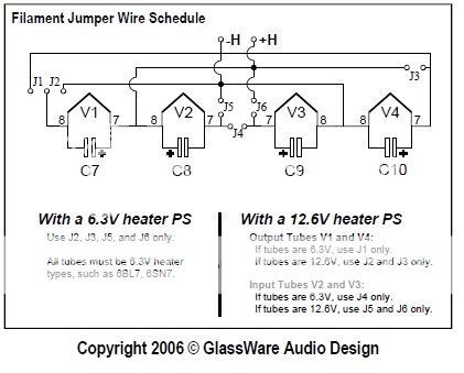
This is what the manual says about AC for the heaters:
An AC heater power supply (6V or 12V) can be used, if the
heater shunting capacitors C7, C8, C9, C10 are left off the board, or are replaced by 0.01ìF ceramic
capacitors.
Since you have the caps on both channels this is not likely the cause of one channel failing...
Are the heaters continuing to glow when you loose the signal?
Is the heater transformer up to the task?
Have you measured voltages before and after you are loosing one channel...?
Are the heaters continuing to glow when you loose the signal?
Is the heater transformer up to the task?
Have you measured voltages before and after you are loosing one channel...?
Stixx said:Since you have the caps on both channels this is not likely the cause of one channel failing...
Are the heaters continuing to glow when you loose the signal?
Is the heater transformer up to the task?
Have you measured voltages before and after you are loosing one channel...?
I was thinking not so much the design of having the cap in there, but a cap failing.
I may have noticed one channel not glowing last night, but I am not going to state that as a fact yet.
The transformer should definately be up to the task...it is a 5A model. If it wasnt I would think both channels would fail. Thats another reason I am thinking one of those caps in the heater circuit. Each tube has its own cap. Everything else in the circuit is shared by two or all tubes.
JayH3 said:
I have probably gone over things like wires and connections a hundred times. It really does sound like a loose connection sometimes because there will be the slightest output.
This is what the manual says about AC for the heaters:
An AC heater power supply (6V or 12V) can be used, if the
heater shunting capacitors C7, C8, C9, C10 are left off the board, or are replaced by 0.01ìF ceramic
capacitors.
I just re-read my Aikido manual, and you are correct about the caps, although mine says for AC filaments to leave the caps off or use a .1u film cap.
When I recently reworked my Aikido recently, I had one dead channel when I fired it up; it was caused by excessive heat (and cable strain) on one of my coax signal cables (happened to be at the vol pot). The center insulator softened/melted when I was soldering, and the braid sunk in to the center insulator enough to short out the signal.
I got the idea that perhaps one of the pads on the board was not secure so when the resistors heated up and expanded they might pull the pad up and break contact. I did point to point wiring for the whole channel. This did not help.
After poking around I found that if I short out the input for a split second I would regain output. I dont think it could be a faulty resistor, but that is pretty much all that is left.
I dont have a scope but I guess that is the best way to find the problem. What would be the ideal way to do it? Use a two channel scope and compare identical test points between channels?
JayH3 said:I got the idea that perhaps one of the pads on the board was not secure so when the resistors heated up and expanded they might pull the pad up and break contact. I did point to point wiring for the whole channel. This did not help.
After poking around I found that if I short out the input for a split second I would regain output. I dont think it could be a faulty resistor, but that is pretty much all that is left.
I dont have a scope but I guess that is the best way to find the problem. What would be the ideal way to do it? Use a two channel scope and compare identical test points between channels?
Well try replacing that resistor first...
kevinkr said:
Well try replacing that resistor first...
When I say I thought one of the the resistors could be pulling up a pad I wasnt thinking a specific one so I wouldnt know which one to replace. Since shorting the input gets it working again it just doesnt seem like a resistor would be the faulty component....however thats pretty much all that is left.
I will probably end up replacing all of the resistors, but I dont feel like I am really learning anything that way.
I really hoped I didn't have to spell it out but since I do, replace the input resistor first!! It could be open or intermittent - the fact that shorting it temporarily restores operation indicates it is probably open.
There is no reason at all why it could not be a faulty resistor, (even new) or that resistor in particular - your one clue points in that very direction, and while it might turn out not to be the cause, it could very well be the cause and replacing that specific input resistor is the first step in methodically troubleshooting the problem. Should that not resolve the issue then you should carefully measure every single operating voltage on the board for both channels and report the results here. (Just be careful) Measure all voltages relative to B- with the exception of the filament supplies which you should probably measure across the filament pins.
There is no reason at all why it could not be a faulty resistor, (even new) or that resistor in particular - your one clue points in that very direction, and while it might turn out not to be the cause, it could very well be the cause and replacing that specific input resistor is the first step in methodically troubleshooting the problem. Should that not resolve the issue then you should carefully measure every single operating voltage on the board for both channels and report the results here. (Just be careful) Measure all voltages relative to B- with the exception of the filament supplies which you should probably measure across the filament pins.
kevinkr said:I really hoped I didn't have to spell it out but since I do, replace the input resistor first!! It could be open or intermittent - the fact that shorting it temporarily restores operation indicates it is probably open.
There is no reason at all why it could not be a faulty resistor, (even new) or that resistor in particular - your one clue points in that very direction, and while it might turn out not to be the cause, it could very well be the cause and replacing that specific input resistor is the first step in methodically troubleshooting the problem. Should that not resolve the issue then you should carefully measure every single operating voltage on the board for both channels and report the results here. (Just be careful) Measure all voltages relative to B- with the exception of the filament supplies which you should probably measure across the filament pins.
Thanks for the help, Kevin. I will take your advice and try replacing that resistor. I will also take some measurements.
I guess the reason I didnt think it would be a resistor is that I was trying to figure out how shorting the input affected the resistor on a physical level, especially in a fraction of a second, and I couldnt think of a reason it would close an open resistor. If anyone could give me an idea, that would be helpful. When I am learning about something I like to learn how each part work in normal and abnormal operation to make it easier to troubleshoot. I am pretty new to electronics, most of my experience is in machines.
- Status
- This old topic is closed. If you want to reopen this topic, contact a moderator using the "Report Post" button.
- Home
- Amplifiers
- Tubes / Valves
- Have an odd problem with my Aikido.