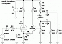
The magic is in the PNP. Which copies any upper error into the
lower half of the phase splitter. Which should hopefully have
the same effect upon cathode feedback no matter which side
of the splitter might see anything unusual.
As the loop sets the impedance, and both haves share the
same correctivity, they should have the same impedance???
The partial feedback loop is entirely DC coupled, and local.
Schady enough you could probably throw a Pentode at it,
and it'd bend right into a Triode emulator. Though there's
nothing wrong with just using a Triode.
The sand here is all abused at unity voltage gains or less.
Only triode and resistors in voltage control of the loop.
The bipolars here are sorta wimpy. But the best if what
LTSpice has in the default library. Could easily do better.
Attachments
This is not all that strange a topology, if it were all N-Ch and/or
Tubage... But I flip the cathodyne (emitterdyne?) upside down.
For the not-so-obvious reason of keeping both ends in the loop.
Bipolars were chosen for Q1 Q2, only cause FETs might add
some gate capacitance to a loop I wished to keep all direct
coupled local feedback with no RC constants.
You could throw a tube at Q2, but it needs more Gm than V1,
if overall loop behavior is to remain "single ended" which was
part of my intent. Single ended with a differential output...
And both outputs sharing the same very low impedance.
The quiescent voltage at the plate of V1 should hover around
75V, which makes the other end of the emitterdyne hover
around 25V. Giving both ends a maximum 50VPP headroom.
Or just slightly less...
R6 is a do-nothing, but drops the dissipation of Q2 under
1/2W. Which is only necessary if you use the wimpy NPN
that LTSpice has in the default library, and as show in my
drawing. Bigger transistor could easily handle the full rail.
And a bigger transistor for Q1 with scaled down resistors
would give an even lower output impedance. Not that it
isn't quite low already...
What else, what else... Ohyeah! The emitter of Q2 sets
the voltage for the Cathode. As Q2 should have much
higher transconductance, even with r5 thrown in as a
fudge to get the currents to balance. Which probably
wasn't really necessary (to balance currents that is)
So R3 has almost nothing to do with "Cathode bias" in
the conventional degenerative sense, its just following
Q2. The degeneration voltage comes from the loop.
I dunno, overSchading of a Triode... Might be too linear?
When does too much of a good thing risk sounding sterile?
Even with such a small 4K7 plate resistor, and never too
linear 6DJ8, the 2nd harmonic is down -60db, not the most
single ended behavior ever seen for a single ended circuit...
Probably cause I cut the gain down from 18 to 6 (per end).
Schading a Pentode or Depletion FET into a Triode might
have been the more appropriate voltage control element
for this partial feedback loop. And the result more faithful
to real (really big) Triode, oddly enough...
The emitter of Q1 acting as-if a normal Triode's plate.
Complete with Mu and the "4th Circuit" intact. Yes it
interacts with the load, just as one might expect of
a low Mu Triode. And the resulting low impedance.
The collector of Q1 acting as-if a plate of Equal dynamic
resistance and mirror opposite Mu. Another incarnation
of the Anti-Triode? I guess thasts why it can work at all,
since there isn't any other differential circuit here in the
conventional sense...
--------------------------------------------------------------
The 6DJ8 doesn't bias with enough legroom under the
cathode. Can't quite get the outputs to swing the full
50VPP because of it. When I respin this loop around a
Pentode, I need to address that biasing matter as well.
Looks like a standard SS unity gain buffer re-configured for some gain using the resister divider R9,R10. V1 and Q2 forming the usual diff. amp stage, and Q1 the follower output. Would be a little cleaner with R4 replaced by a CCS and Q1 replaced by a Mosfet. But I guess you want bipolar Q1 current dividing the load for the triode.
With a bipolar Q1, the emitter and collector current will be a little different for splitting due to the base current. Could fix that by slightly loading the emitter side with another similar bipolar's base and a fake load resistor (R7 +R8) on it's emitter. So it draws off the same base current, leaving the splitter currents thru their resistors matched then.
Don
Yeah, feeedback is like the circuit you describe. Except for the
emitter of Q1 deliberately facing the "wrong" way, for reasons
of keeping the top end in the loop as previously described. It
is unusual, not for having gain, but for splitting with equal Z's.
It has one defeating weakness, however. I havn't figured any
simple way around it (yet). The PSRR is just awful. Any noise on
the top rail, and watch it intermodulate with both outputs. Yuck!
If I could get it all common with either the top or bottom rail,
or even just common to each other, it wouldn't matter. But is
somewhere lost inbetween. And both in opposite phase as
the emitterdyne then mirrors the garbage to the ground side.
Partial feedback doesn't seem strong enough to correct.
-------------------------------------------------------------
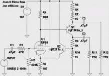
My current variant running in the background is bent around
an EF86, turning it into a pseudoTriode. But the actual plate
is still very much a high impedance Pentode, and latches hard
if R4 behaves too much like a CCS.
Q1 could be a mosfet, sure... But you start adding capacitive
gate+stopper RC constants to the loop, and its no longer a
"local" feedback in the strictest sense. GNF was not what I
was after... Thats the only reason for the Bipolars.
- Status
- This old topic is closed. If you want to reopen this topic, contact a moderator using the "Report Post" button.

