Do you guys think it possible for me to cut this schematic in half (just after the 22nF cap located at the 'MASTER VOLUME') to "steal" the preamp section to use it as a tube based guitar pedal?
For the PSU section, I'll just 'slice' it at the red secondary that connects to the power amp, just next to the 'STANDBY' switch.
Would I be in danger of killing anything?
http://www.fusionstream.org/JCM800_2204.gif
For the PSU section, I'll just 'slice' it at the red secondary that connects to the power amp, just next to the 'STANDBY' switch.
Would I be in danger of killing anything?
http://www.fusionstream.org/JCM800_2204.gif
firethorn said:Do you guys think it possible for me to cut this schematic in half (just after the 22nF cap located at the 'MASTER VOLUME') to "steal" the preamp section to use it as a tube based guitar pedal?
It will only be mediocre at best. The problem with "cutting" it at that point is that you are not leaving an active stage in the circuit to present a constant impedance load to the tone stack and volume. So it will sound different depending on what you plug it into, and if you plug it into something signficantly lower in impedance, let's say not a tube or FET, it will sound horrible, with lots of frequency rolloff. The other problem is that this is not a way to achieve the sound of a real stack. If you cut it at that point, what about the sound of the phase splitter being overdriven? What about the sound of the output transformer being saturated? What about the bass boost and mid dip of a Marshall 4x12 box?
firethorn said:For the PSU section, I'll just 'slice' it at the red secondary that connects to the power amp, just next to the 'STANDBY' switch.
Need more details; from your description, I don't see how that could work.
I love this forum.
Actually, for the moment, I'm not trying to recreate the Marshall sound by cutting out the "engine". I'm trying to understand how it all works because from what I understand, the preamp is a somewhat modular component that can be stacked (or added) later on, so I'm thinking it's not totally wasted for me to try to build it because it can be reused, either by itself or as stated, part of a future amp project.
I'm trying to get a situation where I can overdrive the tube to alter the sound going into (probably) any other guitar amp. Trying to get a feel of how it works, compared to solid states which look pretty simple from what I've seen so far (although took me a while to grasp the concept of course). Perhaps a mildly complicated dummy load to maintain consistency will be needed? Think I have to read up on this anyway.
For the PSU. I think I'm bypassing the amp side on the B+ line, heading straight to 2W 10k resistor (just below the title of the schematic). I'm also bypassing the ground line of the amp but am unsure if the little "bias" knob also biases the preamp tubes.
Think this would probably involve some math in recalculating the neccesary voltages with the power amp missing.
Are you bulding this from scratch or tearing apart an existing amp?
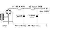
For a Power supply see my quick sketch using 1/2 of the tranny in the schematic or a similar 320V tranny, Bridge Rectifier and a few resisitors and caps.
The B+ of 390V would then follow the rest of the schematic as you noted.
For a Power supply see my quick sketch using 1/2 of the tranny in the schematic or a similar 320V tranny, Bridge Rectifier and a few resisitors and caps.
The B+ of 390V would then follow the rest of the schematic as you noted.
Attachments
firethorn said:Perhaps a mildly complicated dummy load to maintain consistency will be needed? Think I have to read up on this anyway.
Just a simple cathode follower will do it. A lot of the vintage amps use a 12AX7 CF, just connect the plate to B+ and use a 100K cathode load. A 12AX7 CF is frowned on for hifi, but almost anything works with a guitar amp if you want a dirty sound. If you want more beefiness, use something like a 12AU7.
firethorn said:For the PSU. I think I'm bypassing the amp side on the B+ line, heading straight to 2W 10k resistor (just below the title of the schematic). I'm also bypassing the ground line of the amp but am unsure if the little "bias" knob also biases the preamp tubes.
Think this would probably involve some math in recalculating the neccesary voltages with the power amp missing.
If you cut out the PS choke, you will also get less filtering of AC noise. If you use a transformer rated for a Marshall stack, it will be underutilized because your load is so much smaller. I would design something from scratch with PSUD II
firethorn said:
I'm trying to get a situation where I can overdrive the tube to alter the sound going into (probably) any other guitar amp. Trying to get a feel of how it works, compared to solid states which look pretty simple from what I've seen so far (although took me a while to grasp the concept of course). Perhaps a mildly complicated dummy load to maintain consistency will be needed? Think I have to read up on this anyway.
Why not try a simpler project.
I built several variations of the
Real McTube
The work Fred Nachbaur(rip) posted on the web was very insightful and was a great low cost way to get a wide range of results.
His documentation explained enough to inspire the hours of tinkering.
- Status
- This old topic is closed. If you want to reopen this topic, contact a moderator using the "Report Post" button.
- Home
- Amplifiers
- Tubes / Valves
- Stealing a preamp