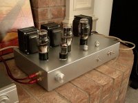
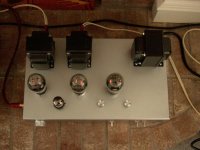
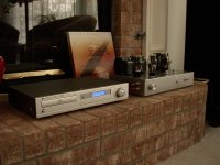
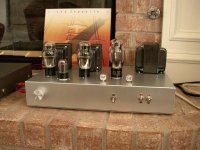
Well I finally got all my parts in last week, redesigned the power supply, and changed the 2A3 B+ and bias. I finished soldering last nite at around 11:30, plugged in my test tubes, hooked up a speaker and a portable cd player and.... Wam!!! sound!!! I was really surprised that it would work at all on the first attempt. So now its working very well, although the hum is a little higher than the PSUDII predicted 8.4mV; this problem will soon be corrected when i change the 5H choke to a 15H. In addition, after hooking it up with the proper components (Cambridge Audio D500-SE, and Boston Acoustic VR-975 Lynnfield Speakers) and plugging in the right tubes (all NOS, JAN Phillips 5691, Sylvania 6A3's, and JAN Sylvania 5U4G) I was blown away by the sound, so transparent, so smooth, now I know what all the hype is about DHT triodes. Although I was in a state of mania while soldering and didnt take pictures of the progress, here are some pics of the final result, in addition to the schematic.
Attachments
That looks really good! I'm thinking of tackling a 2A3 amp soon, and this is a schematic that I hadn't seen before. I have a few questions:
* Is that a standard Hammond aluminum chassis? What finish did you put on it? It looks pretty nice. Also, what tools did you use to for the metalwork?
* What are the two knobs on top - the hum trimpots?
* What do all the switches do?
* Could you post some pictures of the wiring inside?
Thanks,
Saurav
Saurav said:That looks really good! I'm thinking of tackling a 2A3 amp soon, and this is a schematic that I hadn't seen before. I have a few questions:
* Is that a standard Hammond aluminum chassis? What finish did you put on it? It looks pretty nice. Also, what tools did you use to for the metalwork?
* What are the two knobs on top - the hum trimpots?
* What do all the switches do?
* Could you post some pictures of the wiring inside?
Thanks,
Saurav
The chassis is Hammond, but steel, I didn't think the aluminium version would hold the transformers without sagging. The finish is automotive pearl silver spray paint. For tools i used a drill press, hand drill, drill bits including hole drills (1 3/8" and 1") for the socket holes, i used a rounded file to finish the holes of and to bring the 1" hole to the 1 1/16" needed.
You're right about the knobs, they're hum trimpots. The switches left to right: filament voltage selector (2.5V/6.3V) to be able to run 2A3's and 6A3's, HV winding to rectifier, primary winding switch. Pics of the insides might be added later, check previous posting about manic soldering rush, hehe.
Ceramics
Dmitry:
Those look like ceramic sockets in there") That puppy looks nice man. You do excellent work. Thanks for sharing the schematic. I may rewire mine one day and try yours out. You've got more guts than me. I have to walk away for a while and recheck later before I hit the switch. On second thought, perhaps I have more patience than you
That puppy looks nice man. You do excellent work. Thanks for sharing the schematic. I may rewire mine one day and try yours out. You've got more guts than me. I have to walk away for a while and recheck later before I hit the switch. On second thought, perhaps I have more patience than you
Dmitry:
Those look like ceramic sockets in there
That puppy looks nice man. You do excellent work. Thanks for sharing the schematic. I may rewire mine one day and try yours out. You've got more guts than me. I have to walk away for a while and recheck later before I hit the switch. On second thought, perhaps I have more patience than youGood show, Dmitry!!
That's a nice, professional looking amp!
>>>...I was blown away by the sound, so transparent, so smooth, now I know what all the hype is about DHT triodes...<<<
Yep, the same thing happened with me when I fired up my 2A3!! That's why I started stocking up on 2A3's as spares.....
>>>...although the hum is a little higher than the PSUDII predicted 8.4mV...<<<
Hmmm, you might try SLIGHTLY adjusting the position of some of the wires inside, particularly the heater wires for the input valves. I had 4mV of hum in mine in one channel when I started, and have since dropped it to somewhere between 1-2mV by doing just that, along with a couple of other things. You might also make sure that your trafo's cores are in good electrical contact with the chassis, and make sure that your signal leads are well clear of even the B+ line, in case the residual ripple is coupling to it. Have you an oscilloscope so that you can see if the ripple is 60 cycles per second or 120 cps? That will tell you a lot about the origin of the unwanted noise.
Good luck and all the best,
Morse
PS: You might consider fullrange speakers (like one of the 6.5" drivers in the Fostex line) next - that was the next big step up in terms of sound quality with my system after the 2A3.
Skippy,
Thanks for the compliment! Also, those all are ceramic sockets, never used anything but ceramic. As for patience, I have very little to none, but I have found out that I (so far, knock on wood) solder 100% correctly, hopefully it stays this way.
Morse,
Although I do not have an oscilloscope, I do know what you are talking about with moving the wires around, and as you can see the PS and the audio section are somewhat spaced out and on opposite sides of the chassis. I will have to find some time to dig through the insides again soon.
Thanks for all the input!!!
A little clarification....
Hi Dmitry;
No offence was intended about your layout - it looks fine to me!
What I was referring to primarily was the placement of the 6.3V heater wires. If you're using AC heating (as I do), you might find that a shift of as little as 1/4" to 1/2" will drop your hum level. That was exactly my experience - the heater wires were just a LITTLE too close to the signal leads at the socket of the right 6SL7 on mine.
In my case, I just (CAREFULLY) bent the tabs on the underside of the sockets a trifle to keep the 6.3V wires a little further away from the signal leads to the 6SL7's. Also I shifted the signal leads just a little further away - since I can't see your wiring, I don't know if you already did this.
Also, I found that a shift of 3/4" in the position of the secondary from the HT trafo to the B+ switch had about a 1mV effect on hum level. It was just a little too close to the PS choke in it's former position (even though it was almost 3" away at it's nearest approach to start with!).
All the best,
Morse
Morse, I didnt take offense, and sorry if it seemed that way, I was just sayign I planned the layout to avoid hum and all that nasty stuff. I decided to go and try your suggestions, sadly did not help much, so I guess I'll get a bigger choke and see how that fares.
Fdegrove, haven't tested it with 2A3's, and I dont know about inductive coupling, after all the PT is 90 degrees in relationship to the OPT's, or am I missing something?
Anyway while I was in there I took a pic, here you go.
Fdegrove, haven't tested it with 2A3's, and I dont know about inductive coupling, after all the PT is 90 degrees in relationship to the OPT's, or am I missing something?
Anyway while I was in there I took a pic, here you go.
Attachments
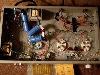
Mig...first of all your amp looks very nice!!...Job well done....If I could give you hints on why you "MAY" be getting noise is that your wiring and placement of components needs to be straightened up....you have too many wires all over the place and its just an invitation for noise.......maybe some perf board and tie wraps would do the cure and you would be set!!!
Cheers!!The DIRT®
Cheers!!The DIRT®
Hi Dmitry;
No problem; I was afraid I'd been a little cavalier with my comment about wiring. I remember how long I agonised over the layouts of my 2A3.....
Sorry to read that the 'hum monster' is still with you. Yep, sounds like you've got a good plan there. FWIW I'm using a 10H Hammond 193M in mine.
Those PS filters look really familiar!! I'm using Sprague Atoms, too! You might add some .1uF 800V bypass caps (series pairs of .22uF 400V film and foil caps) in parallel to the main filter caps - I did and was really happy with the results.
One other "little tweak" that worked wonders to make a smooth sound even smoother and more pleasing was the fitting of an "X rated" safety cap to the mains in; I've standardised on .1uF 250VAC Panasonic brand class X2 interference filter caps in that role and am very pleased at the results of a 90 cent capacitor!
One word of warning for anyone reading this: under no circumstances should a non "X" rated AC safety cap be used in that role; some of the things that make an "X" cap what it is are a built in tendency to fail open as well as fire retardent potting. Any other type of cap is a fire hazard as an AC mains filter!
Anyway, good luck on your amp! It looks like a winner!
Morse
No problem; I was afraid I'd been a little cavalier with my comment about wiring. I remember how long I agonised over the layouts of my 2A3.....
Sorry to read that the 'hum monster' is still with you. Yep, sounds like you've got a good plan there. FWIW I'm using a 10H Hammond 193M in mine.
Those PS filters look really familiar!!
I'm using Sprague Atoms, too! You might add some .1uF 800V bypass caps (series pairs of .22uF 400V film and foil caps) in parallel to the main filter caps - I did and was really happy with the results.One other "little tweak" that worked wonders to make a smooth sound even smoother and more pleasing was the fitting of an "X rated" safety cap to the mains in; I've standardised on .1uF 250VAC Panasonic brand class X2 interference filter caps in that role and am very pleased at the results of a 90 cent capacitor!
One word of warning for anyone reading this: under no circumstances should a non "X" rated AC safety cap be used in that role; some of the things that make an "X" cap what it is are a built in tendency to fail open as well as fire retardent potting. Any other type of cap is a fire hazard as an AC mains filter!
Anyway, good luck on your amp! It looks like a winner!
Morse

cdeveza said:...try using 220uf/450v after the choke and see if it would help.
Yuck! 220uF is 180uF too much, IMO.
- Status
- This old topic is closed. If you want to reopen this topic, contact a moderator using the "Report Post" button.
- Home
- Amplifiers
- Tubes / Valves
- Finally built my 6SL7, 2A3/6A3 amp