mikvous said:Difficulties on matching is not my experience.Main problem is that in my case could not make them stable without over 3.3K grid stopers on both grids.I've made a few different implementations of this tube and to my ears and system sounds as follows:
1. B+ 340v ,7.5 k anode load ,cathode 1k unbypassed .
Sound was dull and borring with no excitement.
2. B+ 220v, CCS loaded like the one on post #30,cathode 500
Ohm bypassed with 470uf Black gate non polar.
More live sound a bit harsh.This impementation also
presented exesive hiss.
3. Same as #2 but ccs loaded with IRFP9240 cascode like the one
my good friend Salas designed.
Hiss was gone, no harsh, more balanced sound.
Have to do more serious listening on this but it seems much
better over all.
Power supply is the same on all the above: rect 5R4 GY >20 uf> 10 H> 440uf> Maida style regulator .
i also had some problems with MJE, 2N ccs.... but in my case the problems were LED diodes.... they are the key problem there (in my opinion).... try to put some small cap's accross them (like 100nF multilayer)... the hiss should be gone....
also because not feeling fine with that type of the ccs i will convert it to cascode DN type... hopefully it will work fine....
milen007 said:whats the gain of this preamp? Zin? Zout? thx alot
gain is very near to the mu of the tube.... i can't remember other parameters... i think that Zout is below 1kohm...
Today I saw Mikvous, I went to his place so to align a pair of Apogee Centaurus with new 1m long ribbon elements. We made a new crossover for those speakers. So I had the chance to listen to the 12B4 with the IRFP9240 cascode CCS anode load as well. Its much more alive and musical than before but still smooth. Clearly preferable than his older resistor loaded version. Especially easy to distinguish the differences with the aid of the cone in closed box & ribbon dipole hybrid speaker. I did not hear any hiss on the ribbons, but such tall elements usually constrict their average last octave energy in the far field in comparison with the rest of their power response. My room measurements confirmed that. Mikvous assured me that with his Seas 8 inch & Peerless HDS speaker (another project we did together in 2008) he could appreciate some further residual hiss reduction when he implemented some bypasses I recommended as in the attached schematic. Off course I would like to compare the minimal part count DN2540 cascode obvious alternative for any subjective differences, but this will take some time until we get some online, could not get them fast in some local store. As for the LEDs being the obvious hiss culprit in the original BJT CCS, I think it is not that likely, since it had only 2, when the 9240 CCS had 6 and still turned hiss way down even with non bypassed LEDS.
Attachments
milen007 said:hi Salas
sorry guys abit off topic.
the irfp9240, is it the one that your design for high voltage supply (the one i am building)? so that design in also a ccs?
erwin
The HV shunt has same Mosfet for CCS, but not cascode.
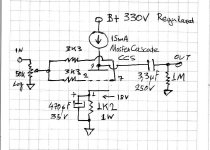
Here it is. The grid stopper resistors are essential. They must be carbon composition and soldered directly to BOTH the indicated pins with minimum leg distance. 3k3 proved OK but some difficult 12B4 may need 4k7 if it still oscillates. Oscillation tendencies proved to be the problem of those valves seeming not matchable. In this preamp previously unworkable 12B4s settled for 1V anode difference between channels for the CCS set exactly at 15mA. You will trim the CCS anode load until you see 18V cathode to ground across the 1k2 cathode resistor. That is 15mA.
Attachments
For CCS we used this one. Elaborate because we still have not got the DN depletion Mosfets that are easy for minimum parts count. Sounds splendid non the less. There may be faster smaller Mosfets too, but those we had on hand. No hiss, great sound so far, even with those. Lower Mosfet needs small heatsink.
Attachments
nice
thanks for the schematic.
questions:
1. what kind of trimmer is that? whats the 145 10% mean? 500ohm trimmer? parallel to 220R resistor?
2. any specific led used? is 3v led ok?
3. can your simple high voltage regulator using the same mosfet be use to supply the 330v to the ccs?
TIA
erwin
thanks for the schematic.
questions:
1. what kind of trimmer is that? whats the 145 10% mean? 500ohm trimmer? parallel to 220R resistor?
2. any specific led used? is 3v led ok?
3. can your simple high voltage regulator using the same mosfet be use to supply the 330v to the ccs?
TIA
erwin
1. It is a 220R 0.25W trimmer. The 145 10% means that with 1.7V Leds the actual trimmed value will end up around 145R.
2. Green or red 1.7V 3 pieces as in HV shunt.
3. Of course it can. And it will sound amongst best solutions. Use 60mA constant current running in it, if you gonna use a common Salas HV shunt for both channels.
Regards.
2. Green or red 1.7V 3 pieces as in HV shunt.
3. Of course it can. And it will sound amongst best solutions. Use 60mA constant current running in it, if you gonna use a common Salas HV shunt for both channels.
Regards.
salas said:
2. Green or red 1.7V 3 pieces as in HV shunt.
Regards.
hi Salas
i got a bit problem finding the 1.7v led. will the 2.2v or 3v led do any good?
how bout this one?
Kingbright L-53HD
http://singapore.rs-online.com/web/...d=searchProducts&searchTerm=2285988&x=27&y=14
erwin
The 2V Kingbright ones will not give problems. You will just adjust your trimmer until you can measure 18V from cathode to ground across the 1k2 cathode resistor. When you get that, you got 15mA for sure. In the case of the HV shunt's CCS, just measure the voltage drop across R1 with given LEDS & Mosfet, and then divide by its R value. If the outcome is far more or far less than your target, exchange for the proper resistor value. Don't use stronger than 2V LEDS, unless you understand the circuits well and you can recalculate them, so not to start way off, even dangerously so with standard values I have given.
salas said:In the case of the HV shunt's CCS, just measure the voltage drop across R1 with given LEDS & Mosfet, and then divide by its R value. If the outcome is far more or far less than your target, exchange for the proper resistor value. Don't use stronger than 2V LEDS, unless you understand the circuits well and you can recalculate them, so not to start way off, even dangerously so with standard values I have given.
hi Salas
thanks alot for the confirmation. you are the man
will just play safe and get the 2v kingbright
 cant find those locally.
Sorry guys OTT
for the HV shunt's, whats my target voltage drop across R1?
anyway thanks again
Erwin
milen007 said:3. can your simple high voltage regulator using the same mosfet be use to supply the 330v to the ccs?
TIA
erwin
In the original HV shunt thread I forewarned that for handling over 300V Vout, the MPSA 93 goes over max and someone must employ a 400V PNP like MPSA 94 or 2N6520 (350V) etc. I hope that you noted that, and also that you will need 380V DC input to the reg for good quality 330V output.
milen007 said:
Sorry guys OTT
for the HV shunt's, whats my target voltage drop across R1?
anyway thanks again
Erwin
Your voltage drop is governed by the target CCS current you look for. Say you have a 47R for R1 and you look for 60mA (double the 2X15mA needed for 2 12B4 channels, so to perform nicely). It will be OK to measure 2.82-3V for instance.
- Status
- This old topic is closed. If you want to reopen this topic, contact a moderator using the "Report Post" button.
- Home
- Amplifiers
- Tubes / Valves
- 12B4 Preamp