philipbarrett said:Jim McShane? Where can we find this gentleman?
google - Jim McShane - tubes ......
first hit !

http://tiny.pl/vnpg
philipbarrett said:Jim McShane? Where can we find this gentleman?
Here! Jim is 1 of the GOOD guys in this hobby. He's as straight a shooter as they come.

Zen Mod said:
Just thought you were referring to someone on this forum for which I searched so ROFL yourself!
philipbarrett said:
Just thought you were referring to someone on this forum for which I searched so ROFL yourself!
considering that English isn't my native ....... I must admit that meaning of your post is sorta slipping away from me ...........
anyway - I know Jim ages ago ........ when we both were Rodents at R.A.T.
real Gent and man who knows his .... biz .
freakyone said:Hello
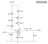
Has any one tried this one,
Or maybe just your thoughts on it.
Cheers
i have a same schematic and similar values preamplifier in my system - a monster preamplifier...... really, really good.......
psu that you presented could be better .... (other tubes, bigger cap's)....
freakyone said:Thanks Sparkle
Just a quick question, is the schematic complete, not missing anything is it?
cheers!
i have a capacitor in parallel with the cathode resistor....470uF Black Gate.... and a gri stopper 2k2 carbon composite.....0,47uF coupling capacitor is a bit low... better use 1uF (this is if you plan to use amps with lower input impedance).... also use 1M resistor to the ground, after the volume control ..... also the 50k resistor is not the same (don't remeber the value), cathode resistor is 1k5 in parallel with 1k, and i do not know which one i have used for R2 but my current is aaround 22mA (from what i can remember).....
be aware - LED diodes can sometimes produce problems in this ccs.... i have had numerous problems with them - but this ccs sounds great in this circuit... because of it - my next project is to remoe that ccs and use DN2540 cascoded ccs in there......
btw. the capacitors in the psu need to be bigger... i am using 100uF as the second cap - also have a monster inductor for filtering ( i believe it is arround 80H double C core).....
freakyone said:Hello
Has any one tried this one,
Or maybe just your thoughts on it.
Cheers
A friend tried that yesterday and told me that sounds more alive with the MJ BJT CCS of the schematic than with a load resistor, but got some hiss also.
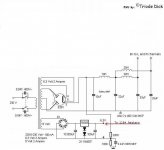
Since he has got only IRFP parts and leds in his bin and no easy access to DN depletion Mosfets, I have drawn this in the attachment for him. If it will work any better, he will let you know I guess, he is a member here.
Attachments
In discussing what types to use, has anyone made the point that 12b4s test absolutely all over the place, within a huge range. Your mission, should you choose to accept it, is to find two that measure equally! That's the starting point, the rest is luxury. the point I'm making is thay're a pig to match and you may need to buy several to get some good matches
andy
andy
Difficulties on matching is not my experience.Main problem is that in my case could not make them stable without over 3.3K grid stopers on both grids.I've made a few different implementations of this tube and to my ears and system sounds as follows:
1. B+ 340v ,7.5 k anode load ,cathode 1k unbypassed .
Sound was dull and borring with no excitement.
2. B+ 220v, CCS loaded like the one on post #30,cathode 500
Ohm bypassed with 470uf Black gate non polar.
More live sound a bit harsh.This impementation also
presented exesive hiss.
3. Same as #2 but ccs loaded with IRFP9240 cascode like the one
my good friend Salas designed.
Hiss was gone, no harsh, more balanced sound.
Have to do more serious listening on this but it seems much
better over all.
Power supply is the same on all the above: rect 5R4 GY >20 uf> 10 H> 440uf> Maida style regulator .
Nice to know that the 9240 cascode CCS anode load worked best for you. You probably mean that you needed 3.3k (or over) grid stoppers on both 2,7 pins. By adjusting the trimmer you can listen to other bias points as well. I would use a very small sink on the lower Mosfet for long term reliability for this CCS. Maybe I will try that CCS load on my 6V6 preamp too. Interesting to compare the anode resistor signature to a Mosfet cascode CCS active load. It can stand 400V across it, so it can be applied to many stuff.
P.S. If anyone else attempts it, please keep in mind that the 4K5 resistor shown on the circuit is virtual. It just represents the 12B4 that must be connected in its place. Also I think that the 12B4 has a higher rp (around 5.5-5.7K in such a circuit) and will develop maybe 25V more on its anode than shown on the original BJT CCS schematic with the 20mA bias it recommended.
P.S. If anyone else attempts it, please keep in mind that the 4K5 resistor shown on the circuit is virtual. It just represents the 12B4 that must be connected in its place. Also I think that the 12B4 has a higher rp (around 5.5-5.7K in such a circuit) and will develop maybe 25V more on its anode than shown on the original BJT CCS schematic with the 20mA bias it recommended.
- Status
- This old topic is closed. If you want to reopen this topic, contact a moderator using the "Report Post" button.
- Home
- Amplifiers
- Tubes / Valves
- 12B4 Preamp