Some folks have used a small 6v or other low voltage mains transformer in inverted fashion off the heater windings - one needs only a few mA so it does not need to be expensive. You could also use a series capacitor and diode pump circuit off one 435 tap - but the capacitor had better be good and h.v. (>700V). I do not have such a circuit handy right now; there are several variations. But the inverted transformer solution might be the more elegant.
http://www.aikenamps.com/BackBiasing.html
This will only give me -9--13volts if I am looking at it correctly and I need to bias the EL34's.
Diode pump circuit? Don't know what you mean.
I was thinking that I saw a circuit somewhere that used a voltage divider off the AC and then one diode and then went to the bias circuit. Maybe I'm wrong :
:
I don't have the room for even a small transformer on or under the Dynaco chassis.
This will only give me -9--13volts if I am looking at it correctly and I need to bias the EL34's.
Diode pump circuit? Don't know what you mean.
I was thinking that I saw a circuit somewhere that used a voltage divider off the AC and then one diode and then went to the bias circuit. Maybe I'm wrong
:I don't have the room for even a small transformer on or under the Dynaco chassis.
I don't have the room for even a small transformer on or under the Dynaco chassis.
Use an AC "wall wart" and a voltage multiplier to generate the negative rail.
Another option is to SS rectify the B+ and self bias the "finals".
OK
When I mentioned a small transformer I was thinking about a 3/4" by 1" square little thing we have available here; about 1VA, but of no use if you cannot obtain the same.
Yes, the bias circuits shown in the quoted piece subtracts from the original h.t. In that sense one might as well use a power zener as a cathode bias source.
Perhaps I will find time later tonight to hook up something with a series capacitor as in what I described earlier and let you know (it is now 19:18 SA time).
Burnedfingers,
If you go "schematic heaven" and look up a Marshall JTM45 you'll see what you need as long as you are NOT using a bridge. The JTM45 uses a 220K Ohm resistor to knock down the voltage to the bias diode, you may need a larger one due to the higher voltage of your xfmr. What type of wire did you end up finding? I was going to offer you some Teflon coated stuff but without the correct strippers it's kind of a pain.
Craig
This will only give me -9--13volts if I am looking at it correctly and I need to bias the EL34's.
It depends on the voltage of the zener.
You'll need a 25W zener - or you can use a resistor, which will effectively be cathode bias rearranged... with the voltage you have, dropping off 30-40V may be a GOOD thing...
Either way you do this, It will generate SERIOUS heat, plus it will take 30-40V off the plates. I've tried this and it's not worth it.
I've used a 25.2V, 2A Radio Shack tranny which can generate up to -66V with a doubler circuit. And it can also serve as some nice clean DC for the preamp tube filaments.
~John~
I've used a 25.2V, 2A Radio Shack tranny which can generate up to -66V with a doubler circuit. And it can also serve as some nice clean DC for the preamp tube filaments.
Can you tell me how to do this? I've never done a doubler circuit before and certainly not a negative supply. Could you post your circuit and parts values?
In a prior post I posted a circuit that made a negative bias supply off of the secondary of the power transformer. This so far has not prompted any discussion as to its merits so I guess its not the thing to do and the Radio Shack route is the way to go.
burnedfingers said:http://www.aikenamps.com/BackBiasing.html
This will only give me -9--13volts if I am looking at it correctly and I need to bias the EL34's.
Diode pump circuit? Don't know what you mean.
I was thinking that I saw a circuit somewhere that used a voltage divider off the AC and then one diode and then went to the bias circuit. Maybe I'm wrong
I don't have the room for even a small transformer on or under the Dynaco chassis.
That is just an example.
Back-biasing is a good solution if you go for Class A1 or moderate Class AB1 operation (i.e. the anode current at max output should not be greater than the idle current). In that case it is almost as good as a classical fixed bias. Actually this is more the case for triodes or triode-connected pentodes.
For UL or pentode connections you always have a more variable g2 current which can easily double at max output.
It will give you just any voltage you need by changing the resistor that connects the center-tap to the ground (according to the total voltage you have and the currents you need). The higher the voltage drop the lower the effective anode voltage supply will result, of course.
You have just to find a good quiescent point for your amp and the "right" rectifier in order to get the supplies you need.
For example, triode connected EL34's at max. plate dissipation require 400V anode voltage and 30V bias. So you need at least 430 Vdc.
In that case the idle current should be 70 mA per valve. Then, to get 30V bias, the resistor should be at least 215 ohm. With a slightly higher value for both total DC supply and drop resistor, you will have some additional drop which will allow for some regulation (together with additional filtering).
45
Can someone explain the pros and cons of using a rectifier tube as a means of a negative bias supply?
I saw a schematic of a Grommes 215BA that uses a 6X5 by putting an AC voltage to the cathode and getting a negative voltage off the plates. I cannot however see the value of the cathode resistor on the schematic but I think its 10K.
I saw a schematic of a Grommes 215BA that uses a 6X5 by putting an AC voltage to the cathode and getting a negative voltage off the plates. I cannot however see the value of the cathode resistor on the schematic but I think its 10K.
burnedfingers said:I have an HP transformer that I am using in a Dynaco stereo 70 that I am putting together. It doesn't have a bias supply tap.
Can I make one by coming off one of the AC secondaries? Its 435-0-435 AC secondary.
Can someone help me out here?
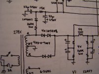
I used a very simple setup in a design I did in the early 90's.... a 0.03uF film cap (orange drop) from one of the secondary ends in series with a 43K resistor to ground. At the junction of the 0.03uF cap and 43K resistor, take a diode for rectification to a 50uF cap to ground. From this point, use a series resistance of about 40K between a pot and fixed resistor(s)... take your adjustable bias for the pot wiper to another 50uF cap... it will easily bias a pair of EL-34 tubes. It's been working on several amps for over 15 years... has never failed and doesn't make a lot of heat either.
Regards, KM
burnedfingers said:Can someone explain the pros and cons of using a rectifier tube as a means of a negative bias supply?
I saw a schematic of a Grommes 215BA that uses a 6X5 by putting an AC voltage to the cathode and getting a negative voltage off the plates. I cannot however see the value of the cathode resistor on the schematic but I think its 10K.
Love that amp - not too many commercially available triode-wired 807 designs out there. Here's the bias scheme. Cathode resistor (R41) is actually 68K.
An externally hosted image should be here but it was not working when we last tested it.
burnedfingers said:I have an HP transformer that I am using in a Dynaco stereo 70 that I am putting together. It doesn't have a bias supply tap.
Can I make one by coming off one of the AC secondaries? Its 435-0-435 AC secondary.
Can someone help me out here?
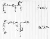
here are the old-school variations...just google on fender bias circuit or marshall bias circuit etc
Attachments
- Status
- This old topic is closed. If you want to reopen this topic, contact a moderator using the "Report Post" button.
- Home
- Amplifiers
- Tubes / Valves
- Need a bias supply how??