Hi, I am in the process of an experimental design of a valve over drive circuit., Im using 2 12ax7 valves (4 triodes), with potentiometer between the 2 valves for a drive control.
By putting a sinewave into the input, I get a clean output at the volume control between the valves, and a varying output after the second valve, depending on the level of the pot.
the output has an overdriven top section of the waveform from about half way on the pot and the bottom section getts bigger, but near to full on the pot, the bottom of the waveform decreases again (but doesnt ever clip like the top does).
Any help with why this occurs and how to fix it would be greatly appriciated.
Ollie
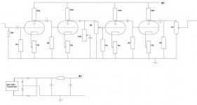
Here's the schematic I've draw of the circuit, the cathode resistors for the second valve are 5.6k fixed, not 10k pots as drawn because maplin only had 2 of the pots. The pots on the first valve are set at about 6k, although the problem occurs even when they are set at 10k.
Obviously I should do the maths to work out the bias settings, although as I'm fairly new to this sort of thing, I'm not quite sure how to do it.
I'll try to get a picture of what the scope shows as well
Obviously I should do the maths to work out the bias settings, although as I'm fairly new to this sort of thing, I'm not quite sure how to do it.
I'll try to get a picture of what the scope shows as well
Attachments
It now works properly, well almost, bias needs tweaking a little to optimise. I've also removed the tone pot, and i might put a bypass switch from the first stage to the output.
If anyone could enlighten me as to the maths around valve amplifier design. eg, how do you know what valve the cathode and anode resistors need to be. and how do you work out the gain.
That would be greatly appriciated
Ollie
If anyone could enlighten me as to the maths around valve amplifier design. eg, how do you know what valve the cathode and anode resistors need to be. and how do you work out the gain.
That would be greatly appriciated
Ollie
http://www.aikenamps.com/CommonCathode.htm is a good document on preamp design. Note that since you are using this circuit for overdrive, there is not really such thing as "right" biasing, whatever sounds good for you is fine. Pretty standard value for cathode resistor of ECC83 is 1,5 kilo-ohms but often there is one stage with a 39k cathode resistor, literally rectifying the signal but not adding much gain otherwise.
You must add attenuators between stages, otherwise valves are overdriven too much and it will sound like crap. 470k/470k voltage dividers between stages would do. There is so much gain in this circuit that you should not worried about lowering it a bit, all commercial amps use same method etc.
You must add attenuators between stages, otherwise valves are overdriven too much and it will sound like crap. 470k/470k voltage dividers between stages would do. There is so much gain in this circuit that you should not worried about lowering it a bit, all commercial amps use same method etc.
Some more things came to my mind.. As you can see from the document I posted earlier, it is possible to shape the tone of the preamp in several ways like cathode capacitors and attenuators combined with miller effect. When you have built your design I'd suggest you to take advantage of this, generally speaking bass frequencies have to be cut (or mid and treble boosted, which is the same thing) before distortion stages and some treble cut between distortion stages is good so the sound will not be too buzzy when it comes out of the amp.
I'd also suggest to include a tone stack to this circuit because it is quite easy to do and adds a lot of versability. For starters you might want to add more bass to the sound post-distortion and this is an easy way to do it. Soldano SLO 100 is a good high-gain circuit you might want to get familiar with.
I'd also suggest to include a tone stack to this circuit because it is quite easy to do and adds a lot of versability. For starters you might want to add more bass to the sound post-distortion and this is an easy way to do it. Soldano SLO 100 is a good high-gain circuit you might want to get familiar with.
- Status
- This old topic is closed. If you want to reopen this topic, contact a moderator using the "Report Post" button.
- Home
- Amplifiers
- Tubes / Valves
- Output of preamp drops when overdriven