I'd like to convert the output stage in a PCM1793 based DAC from its current OPA2134 to tube. The Dac uses a differential +- output stage and that's the part I can't find any tube info on. I know I've seen posts on how to replace the differential op-amp section with a tube circuit.
Can anyone help?
Can anyone help?
http://www.diyaudio.com/forums/showthread.php?s=&threadid=133373&highlight=
The good stuff begins around Post #81 with a post by Tom S.
I think all the kinks in my version were worked out by Post #90.
Truly a masterpiece of dumb luck. Fantastic PSRR and CMRR.
Seriously, I didn't discover till after the fact that I had pulled
a Broskie and got all the bad stuff to magically cancel out.
Couldn't have designed this good if I was actually trying.
Mind you the power supply is deliberately shown with
absurd amounts of ripple, just to illustrate the rejection.
Your post #95 seems to imply a misunderstanding the theory
of operation regarding my circuit. Specifically where you claim
that it is an SRPP.
It might be more accurately described as a cascoded plate
follower. Differentially bridged into a White cathode follower.
And both "stages" abusing the self same pair of triodes.
An SRPP wouldn't have the extra plate resistor up top of
the totem, nor use feedback from this point to correct the
cumulative error of both a cascode and a cathode follower.
I conclude it has nothing in common with SRPP, aside from
first glance appearances.
You had already shot down the differential cathode follower
plan as having too much THD, what made you go back to it?
kkillebrew said:I'd like to convert the output stage in a PCM1793 based DAC from its current OPA2134 to tube. The Dac uses a differential +- output stage and that's the part I can't find any tube info on. I know I've seen posts on how to replace the differential op-amp section with a tube circuit.
Can anyone help?
Do you like to keep balanced output or not?
kenpeter,
Who cares what if the name is SRPP or not") !
!
It had to much THD in its initial form, just had to be corrected to sim fine. Showed this in post#43:
http://www.diyaudio.com/forums/showthread.php?s=&threadid=133373&perpage=25&highlight=&pagenumber=2 .
The only thing was loosing 6dB but its just fine as output was on the high side from the DAC.
Who cares what if the name is SRPP or not
! You had already shot down the differential cathode follower plan as having too much THD, what made you go back to it?
It had to much THD in its initial form, just had to be corrected to sim fine. Showed this in post#43:
http://www.diyaudio.com/forums/showthread.php?s=&threadid=133373&perpage=25&highlight=&pagenumber=2 .
The only thing was loosing 6dB but its just fine as output was on the high side from the DAC.
I think I've presented about the ultimate circuit for exactly that.
But I have no proof other than the LTSpice simulation as shown.
However, I lack the skill to explain it adequately. A lot of what
it seems to excel at came as an unexpected bonus surprise.
I have never built one, and as far as I know, nobody ever has.
I've written Broskie to see if he wants to tackle an analysis,
and potentially debunk this idea before it wastes anyone's
time on something that won't actually work.
I am too busy at work to bench this right now. My boss would
tear my head off if I was playing with tubes before my regular
work was completed.
I don't have a DAC like yours, but I have an Tek AFG3252 dual
channel function generator on my desk that can fake it.
Look here:
http://www.lampizator.eu/LAMPIZATOR/photogallery/STEPS/Lampizator.doc
Build the alternative setup.( Cathode follower ).
Here his site.
http://www.lampizator.eu/
Steel left signal from pin 18 and right signal from pin 12 of the PCM1793.
http://www.lampizator.eu/LAMPIZATOR/photogallery/STEPS/Lampizator.doc
Build the alternative setup.( Cathode follower ).
Here his site.
http://www.lampizator.eu/
Steel left signal from pin 18 and right signal from pin 12 of the PCM1793.
Mine is shown (simulated) handling 10VPP common mode ripple.
Which implies that it can easily handle 5V offset in either direction.
Though it was designed around 2.5V offset. Whatever...
Its clear that this is a much hated circuit, though no-one has
ever built one or rationally debunked it. Lets keep it that way.
Which implies that it can easily handle 5V offset in either direction.
Though it was designed around 2.5V offset. Whatever...
Its clear that this is a much hated circuit, though no-one has
ever built one or rationally debunked it. Lets keep it that way.
revintage said:The outputs from the DAC are at +1,4V DC so this must be handled if you want to directcouple to a tube. The circuit in my post above was adjusted to that specific DAC that where at over +2V DC. It can be fixed.
The Lampizor does not work with diff outputs.
I would like to use a 6dj8 tube to build this. What adjustments need to be made for the 1.4 v 1793 DAC?
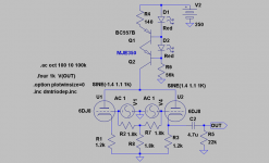
revintage said:This should do it. Signal out will only be 0,4Vrms, THD below.05% with falling overtonespectra.
It looks great when simmed but as kenpeters I have never built it.
Contact sunrise to hear if it it worked like he wanted.
Nice! Thanks. Any kind of spec on that LED? or Just a regular instrumentation red type? I will check with Sunrise.
- Status
- This old topic is closed. If you want to reopen this topic, contact a moderator using the "Report Post" button.
- Home
- Amplifiers
- Tubes / Valves
- Need help with tubed output for PCM1793 DAC