Okay, I took a closer look at your circuit... some constructive feedback:
1- output circuit: you simply took commonly listed class A SE operating characteristics and calculated 18 volts divided by plate+g2 current = 480 ohms. A non-value in 10- 5- or 1% tolerances. Go with a 500 ohm as recommended and increase to 5-watts. Also suggest you don't stack your F3 points for the cathode bypass and input coupling. Would suggest a 50uf/50V cap for bypass. You have not accounted for voltage drop in the OPT... with a plate current of 32ma, and an assumed DC resistance of 350 ohms you'll get more than 11 volts drop. Would recommend a 2.2K 1W resistor in series with g2 to drop the voltage and limit the current. You have a 1meg resistor providing plate feedback, is this to reduce gain, clean up non-linearity, or instability? Lastly, a 1K grid stopper on g1 would not be a bad idea.
2- input stage: as pointed out, it's not biased. Get a set of plate curves for the 75 and calculate an operating point... ensuring that you have adequate grid bias so you don't drive it positive with large input signals. Move the input cap before the pot (already noted) and add an additional resistor across the input jack. Add a bias resistor for the cathode and calculate a bypass value for your preferred F3 point (and don't stack with the other two). The 220pf cap from the plate to ground, what frequency is it calculated for? Do you know that you'll have problems with high-frequency instability? Lastly, the 75 also incorporates dual diodes... you should tie the plates to the cathode (not ground) so they can't have any interaction.
3- power supply... how did you calculate your B+? Using the type 84 datasheet and approximate load per of 40ma, a capacitive input filter would be around 370 volts as you are delivering 300 volts RMS per plate. Your 100 ohm resistor (at 80ma) will only drop 8 volts. Supply voltage is far too high, get the proper power transformer. A DC filament supply is not really needed as you are using indirectly heated tubes. You should make a virtual filament center-tap with a pair of 33-47 ohm resistors to ground and use a tightly twisted pair of wires to drive the filament... feeding the output tube first.
Think about design goals... things like:
- frequency response
- power bandwidth
- overall gain
- power output
- distortion
- signal/noise
- topology, i.e., no-feedback, overall-loop, or single-stage
Hope this helps... it's a starting point, but you can still improve more beyond the above, i.e., filter choke, split the supply (rectifier/filter per channel), tweak the feedback components, bypass the screen supply separately.
Regards, KM
To answer all the questions and provide a little more clarity to my goals here is some info.
#1. This is my first attempt at designing from scratch any amp. I am thinking of purchasing SE Amp CAD since I have used the PP calc from Glassware and find it pretty intuitive.
#2. Most if not all the components are from my "junk box" (which accounts for about 70% of all the tube related stuff I own, LOL)
#3 This schematic is adapted from a few DIY projects that I have worked on in the past. My knowledge is growing in leaps and bounds and since I learn by doing (hence my quote "If I could only figure out how to put the smoke back in) I thought it best to put something together on paper and let the comments/suggestions fly.
#4. My main goal is to get a few watts of power with less than 1%THD and use some more unique looking less used tubes.
Rectifying the filament supply is not an issue as I literally have a BAG full of Bridges and lower voltage capacitors. Assuming the filaments are like light bulbs they tend to like DC (thanks to Edison rather then Westinghouse) and last longer. Using antique tubes and on a shoestring budget tube life is important.
Excuse my ignorance KM, but what do you mean about F3 point stacking? I get the idea about 5 watt W.W. in 500Ohm being more readily available and will note the changes.
By F3 are talking about a center or 3db down point?
Would a 470K input load resistor from input to ground suffice?
Input cap will move to before the Pot but won't I lose low frequency response as they would form an RC filter high pass?
or does the "input" load stop that?
Power Supply holy crud Batman I made a typo in my original notes I was calculating about 370 or so and wrote down 270 which is where I got the 262 to 265 volts. I do need a different tranny!
I see I have a lot to learn.
To sum up
1. I need to know about F3 and how to calculate the bypass caps
2. I will tie the two diode plates to the cathode right on the sockets.
3. I will move input cap to before the pot and add 470K load resistor.
4. I think I have an NOS Gilfillan potted PT that will be more like 500 CT.
5. I will keep CRC filter as Chokes aren't cheap and I have a decent supply of electrolytics and large wattage resistors.
Any other help is greatly appreciated.
BTW, sound quality is not first and foremost in this, the learning experience and unique appearance is actually more important.
Hi CC,
I figured you were trying to use parts on-hand... makes good sense when learning. A few suggestions: Get an old tube manual... the RC-30 is fine and has some good material in the front for calculating bias points, load resistances, output power and distortion figures. SE Amp CAD is a slick little tool but it only works with triode mode and has a limited set of tubes to select from. While it does contain some beam power pentodes, all are defaulted to a triode strap which can not be changed. It won't do any magic and you can do everything the same with a good set of plate curve charts, but it certainly is a time-saver and quite useful.
Note that in most cases the output power listed from data sheets implies 5% THD. As you drop the power the distortion will also drop.
As for DC filaments... not really needed and less complexity without them. I would get things working first and then make additional "nice to have" features afterwards.
The F3 points mentioned are where the lower frequency response drops off as a result of the time constants in the design. In your amplifier there would be 4 of them:
- The input coupling cap to the volume pot
- The cathode bypass cap on the 75 triode (once you correct it)
- The coupling cap driving the 41 output
- The cathode bypass cap on the 41 cathode
A simple formula to use is: F3 = 1/(2pi*R*C) where:
Pi= 3.14...
R= resistance in ohms
C= capacitance in farads
example: 500 ohms and a 50uf bypass cap
1/(6.28*500*0.00005)= 6.4Hz
Stacking means you have all of them set the same... not a good idea. My suggestion would be set the output stage as above... ~6Hz (standard values get you close). The coupling cap to the 41 for ~12Hz. Cathode bypass for the input can also be 6Hz... the input coupling cap to the volume pot is there for DC blocking, nothing else... preferably below 5Hz.
A 470K input resistor is fine... if you're certain you won't have any DC offset present to the amplifier you could omit the input cap. So the input goes across the pot and the wiper goes directly to the grid of the 75.
One last point... add a bleeder resistor to the B+ supply... calculate it so it draws less than 5ma. This is more a safety point... when the amp is turned off, the tubes will stop conducting and may not drain the filter caps completely... so you could have enough voltage floating about to either make a spark if shorted or give you a mild shock if you touch the wrong points.
Other than that... have some fun building it and be sure to consider your mechanical layout. I would also suggest doing a breadboard first. Get some inexpensive terminal strips and mount everything on a board, you can easily wire it up and make changes before committing to the insides of a chassis. Lastly, post some pictures of your progress.
Regards, KM
KM Thanks for all the help! I am relatively new to the vacuum tube thing, started it on a whim a few years ago.
I am only 37 years old so most of this stuff was obsolete even before I was born. I love music and tinkering with things and my sister in law mentioned to me that someone was cleaning out an old house in town and there was one of those "old radios, you know the kind that stand up on the floor" on the curb.
I drove over and picked it up in the trunk of my car. Well, after a few hours on the internet I found out it was a Grunow/General Household Utilities Model 110. So I found a schematic online and started playing around with checking for shorts/opens bad resistors etc. There were a few pretty shoddy looking caps and such but otherwise it seemed fine.
I spent the better part of a week on Ebay buying new caps and NOS or tested good tubes and then Fired it up. Well, it worked!
My parents are the "flea market" Estate Sale type of people one day at a charity "silent auction" I bid on an old repairmans box of tubes. The paper on it said there were some more items in boxes that went with it but I thought nothing of that just that the box was nice looking and had some old tubes, literature etc. I bid $10 and since it was way down the list I figured I would leave and if I won they would contact me. Well, about 3 hours later my parents called and said they had stuck around till the end and I WON the auction and they would drop it off to me in a little while. They said "make sure there is room in the garage". I thought it strange since it was just a box about the size of a microwave but when they got to my house their ENTIRE MINIVAN was full of boxes of tubes!!!
With all these tubes I started tinkering some more. 3 years later I am an ADDICT and there are tubes everywhere in my basement.
My 9 year old daughter has taken to helping with the testing, labeling and storage. She is also learning how to solder and strip wire etc.
Ok, So I do understand the F3 points as 1st Order 6dB/Octave RC /CR Filters. I have experience with them since I used to do a lot of Car Audio and produced my own HP and LP filters. My only question is this.
How do I calculate the Cathode Bias Frequencies? I am used to only one end of either the cap or the resistor being grounded, in this case they are parallel to each other? Which Resistance am I using? The Cathode resistor ? Plate resistance? I am just a tad confused on those.
The stacking makes sense since there would be 12/dB rolloff and if the F3 points were the same some response could be lost.
Any "Rule of Thumb" as to what they should be set to?
I do plan to possibly use this as a "High" or "Treble" amp in a Bi-Amped system so I could calc the input Cap/Volume as a High Pass Filter if need be?
On the bleeder resistor, I ALWAYS assume any CAP is charged even if it has been in a "junk box" for a long time. I went to school to be an Airframe & Powerplant mechanic many years ago and the condensers on Ignition systems can be fun to toss to someone charged...you know "Hey..Catch!!!" The jolt on peoples faces was worth a million bucks!
I made up a little "bleeder" tool of sorts with some old Voltmeter probes and a 2K ohm 20 Watt resistor out of an old "Boat Anchor" I use that to short out all the big caps whenever I have powered something off to play with it.
Since I am the only one to touch these they are safe but as I intend to build a few in the future using all NOS or NEW components for friends and possible sale, I will be sure to place that immediately following the Rectifier.
Again, I thank you for your help! This type of thing is becoming a lost art and I am hoping to continue on into the future as I have found that tubes just sound better!
BTW, I am finishing up a 6V6 PP based on some schematics I found online and will post photos when it is complete.
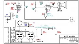
coldcathode said:Ok, having amassed quite a collection of tubes, I thought I'd make a run at developing my own "ST" tube amp. Attached is my first try at designing a single ended amp on my own.
Comments? Suggestions? Am I nuts??
Do you really need as much gain as a 75 can provide? Given the high gain, you're going to have a Cmiller problem with a 500K volume pot, and lose a lot of high frequencies. Also, this type operates at very small plate currents, and won't have enough drive capability to source current to the final at high frequencies, so you have a slew rate problem there as well. Also, local NFB will reduce the input impedance of the final, making it even more difficult to drive properly. It would seem that a lower gain, higher current VT would do better up front. Something like a 6J5.
This project won't require DC heater power. Unless you're dealing with some very small input signals, AC heating will work just as well. In any case, the DC heater supply is way inadequately filtered. Heater DC needs to be very clean otherwise it's worse than straight AC heating since dirty DC introduces all sorts of line frequency harmonics.
The main DC is inadequately filtered. You'd do better with an LC filter after the resevoir capacitor, especially if it's as low as 10uF. Given the RC filter values (100R, 47uF) you're getting just a bit less than -11db(v) of ripple suppression. Also, for this project, a single 5Y3 or #80 would be more than sufficient.
"My main goal is to get a few watts of power with less than 1%THD and use some more unique looking less used tubes."
You can pretty much fugedabouddat. #41's are nasty in SE, as the spec sheet gives a THD= 11% for SE operation. Local NFB will help somewhat, but I doubt it'll give an 11-fold improvement all by itself. (In radio xcvr use, that wasn't so important anyway.) So you're probably looking at including gNFB as well to linear up the final. The other alternative would be to connect the 41 as a pseuotriode. This type seems to work better that way than as a straight pentode.
How do I calculate the Cathode Bias Frequencies? I am used to only one end of either the cap or the resistor being grounded, in this case they are parallel to each other? Which Resistance am I using? The Cathode resistor ? Plate resistance? I am just a tad confused on those.
It's simply w= (Rk)(Ck). This arrangement forms a shelving network with minimum gain at DC (where Ck drops out of the circuit completely) and rolls on to the maximum gain where Ck becomes fully effective. The zero occurs at a lower frequency than the pole, and the pole frequency is given as above. That's the one you have to worry about.
Miles,
As noted earlier, CC is mainly trying to use parts he already has... a learning experience as it were and at a near-zero cost beyond the pieces he has to work with.
CC,
Some good reading in this little article about building a 45 SET... Gordon explains his rational and has some good formulas for calculating bypass values, required slew rates, etc. This article should give you some insight and some things to consider in your project.
Regards, KM
This is all excellent "feedback" (pun WAS intended).
As far as the gain of the 75, I realize that something of a more medium Mu would be better but I suppose I could could use a 27 in its place. This only has a 9 as opposed to 100 in the 75. I just happen to have 5 or six 75's and 2A6's to play with if I blow em' up it doesn't matter. My supply of 27 is limited to 1 plus what is in my Atwater Kent 55C.
1% THD in a tube amp IS hard to get and I am willing to live with the distortion figures of the 41. This is more about "looks" and the fact that I will develop the schematic on my own more or less.
The 27 idea does intrigue me since I can always find more tubes and how often do I actually listen to AM anyway? I think I might have a go at pluging in all this info into another schema and post it up tonight or tommorrow.
Again, I really appreciate the feedback. I think a few more go arounds with this type of thing and I will have enough experience to present less amateur questions.
Hello Miles, Ken here............. this has nothing to do with your latest venture but DIY will not allow me to e-mail you as I am still under 'moderation' anyway, I was downloading your 807 schematic BUT I noticed there is no values for the topology.......... rather important due to massive impedence in knowledge quotient. Might you be able to email with values for the fixed bias 807? Kind regards..........oh .... I will be interested in your latest venture of the single ended design and how the bass response sounds.
cleantimestream said:Might you be able to email with values for the fixed bias 807? Kind regards..........oh .... I will be interested in your latest venture of the single ended design and how the bass response sounds.
Hey Ken:
Send me an e-mail to: ar_phox (at) inbox (dot) com. I can send you all the details about the design you mention here.
The 845 SET project is still very much a work in progress, and it's gonna be awhile until I have any results. As for my existing projects, I'm getting bass that packs plenty of "authority" but without any of the sloppiness that seems to plague VT designs. This being due to the useage of decent OPTs and adequate LF response in the open loop design.
- Status
- This old topic is closed. If you want to reopen this topic, contact a moderator using the "Report Post" button.
- Home
- Amplifiers
- Tubes / Valves
- First Shot at a 41 SE amp