My question is regarding the power supply xfrmr secondary side.
Click on the image to enlarge it.
http://img149.imageshack.us/my.php?image=mypowersupplyfor169aazg7.png
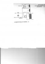
The top most portion of the secondary side of the xfrmr is a 5V@2A Tap. The second/middle section is the 612V ct , and the bottom is the 6.3V@1.2V Tap for the heaters.
My question is regarding the connection between the 612V ct section and the 5V section. The 612V section is rectified. THEN it is routed in series back into the AC 5V supply , after which it is fed into the output xfrmr center tap (B+).
What is the purpose of this ? It doesn't make sense to me. Why would you want to mix a 5V AC signal with the DC B+ voltage ?
Are they using the DC voltage to bias the PS xfrmr ? Am I missing something here ?
I am considering rewiring the PS xfrmr so the 5V@2A section is
seperated from the 612V section , rectified (solid state)which will
bring the voltage up around 6.7V , and use it to provide power for
the heaters, thus reducing hum.
Unless there is some reason the PS secondary is wired how it is , can anyone see anything wrong with this ?
Thanks for any help....................Blake
Click on the image to enlarge it.
http://img149.imageshack.us/my.php?image=mypowersupplyfor169aazg7.png
The top most portion of the secondary side of the xfrmr is a 5V@2A Tap. The second/middle section is the 612V ct , and the bottom is the 6.3V@1.2V Tap for the heaters.
My question is regarding the connection between the 612V ct section and the 5V section. The 612V section is rectified. THEN it is routed in series back into the AC 5V supply , after which it is fed into the output xfrmr center tap (B+).
What is the purpose of this ? It doesn't make sense to me. Why would you want to mix a 5V AC signal with the DC B+ voltage ?
Are they using the DC voltage to bias the PS xfrmr ? Am I missing something here ?
I am considering rewiring the PS xfrmr so the 5V@2A section is
seperated from the 612V section , rectified (solid state)which will
bring the voltage up around 6.7V , and use it to provide power for
the heaters, thus reducing hum.
Unless there is some reason the PS secondary is wired how it is , can anyone see anything wrong with this ?
Thanks for any help....................Blake
You don't commonly see this since the 5V windings usually aren't center-tapped. But it cancels the 60 Hz ripple that would otherwise occur with a directly heated rectifer (it SHOULDN'T be used with an indirectly heated one like the 5AR4). That 60 Hz ripple may not be significant, especially if there's at least two stages of filtering.
Thanks guys !
Tom, the 5v supply isn't the center tapped one. The center tapped one is 6.3v.
I confused myself because I am not running a 5Y3 as a rectifier, but rather a solid state rectifier that has a tube socket base. A "plug-in" solid state rectifier , if you will. I had overlooked the obvious , yet again !
It never ocurred to me that the 5V supply was for the rectifier TUBE !
Since I am not using a rectifier tube, then do you see any issue with me using the 5V supply (with solid state rectification it should be about 6.7V) for a DC heater supply for the rest of the valves ?
Thanks..................Blake
Tom,
Sorry about that. You couldn't see the picture at all, or it was too small and unclear ?
Did you try clicking on the pic, or where the pic was supposed to be ? It will enlarge it to a reasonable size.
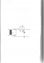
I just tested my "plug-in" ss rectifier. There is NO connection between any pins and pin 2 . I tested with my ohm meter and I tried it in both polarities. Pin 2 is nothing.
I've corrected this schematic to show how my PS is really wired.
Same as previous pic , you need to click on the link, then click on the pic to enlarge it.
http://img340.imageshack.us/my.php?image=mypowersupplyfor169aatk9.png
So my 5V supply IS in series with my B+ , as I incorrectly (but actually correctly") ) suspected.
) suspected.
I'm going to assume I should remedy this, and until I purchase the proper diodes to try to use the 5V tap for heaters , I will attempt something like this :
http://img530.imageshack.us/my.php?image=myrevisedpowersupplyfordr2.png
What say you ?
Thanks again..............................Blake
Sorry about that. You couldn't see the picture at all, or it was too small and unclear ?
Did you try clicking on the pic, or where the pic was supposed to be ? It will enlarge it to a reasonable size.
I just tested my "plug-in" ss rectifier. There is NO connection between any pins and pin 2 . I tested with my ohm meter and I tried it in both polarities. Pin 2 is nothing.
I've corrected this schematic to show how my PS is really wired.
Same as previous pic , you need to click on the link, then click on the pic to enlarge it.
http://img340.imageshack.us/my.php?image=mypowersupplyfor169aatk9.png
So my 5V supply IS in series with my B+ , as I incorrectly (but actually correctly
) suspected.I'm going to assume I should remedy this, and until I purchase the proper diodes to try to use the 5V tap for heaters , I will attempt something like this :
http://img530.imageshack.us/my.php?image=myrevisedpowersupplyfordr2.png
What say you ?
Thanks again..............................Blake
My question is regarding the connection between the 612V ct section and the 5V section. The 612V section is rectified. THEN it is routed in series back into the AC 5V supply , after which it is fed into the output xfrmr center tap (B+).
What is the purpose of this ? It doesn't make sense to me. Why would you want to mix a 5V AC signal with the DC B+ voltage ?
The 5v winding is there to heat the tube rectifier, as you seem to have realized. The B+ output from a tube rectifier is taken from its cathode and, in the case of a 5v tube, the heater may also be the cathode (directly heated, e.g. 5U4) or the cathode may be a separate cylinder around the heater but not electrically isolated from it (indirectly heated, e.g. GZ34). Either way, the 5v winding has to be connected directly to B+. This can't be avoided but does not cause hum, because the 5v winding isn't connected to anything else but the rectifier tube's heater.
Incidentally, with 6.3v indirectly heated rectifier tubes (e.g. EZ81, 6D22S), the heater and cathode are electrically isolated, enabling the 6.3v winding to be shared by the rectifier and other tubes in the amp.
Since you don't use a tube rectifier, you don't need to use the 5v winding. It cna be left disconnected or you could use it for some other pupose.
I would really suggest using tube rectification. In my experience with twiddling with these things tubes sound better. 5U4's are cheap on Ebay and elswhere and if you want more current (can't see why you would need more than 300mA's) you could parallel two 5U4GB's (assuming you have 6+ Amps 5.0V supply) and get about 300VDC @ 600mA!
Thanks for all the info guys.
I've tried a 5Y3 rectifier with stock 80ufd can cap. -VS-. a SS rectifier and 900ufd capacitance.
I can't see (hear ?) any reason why I would want to go back to a tube rectifier.
With a SS rectifier I have a higher B+ , more power supply filtering, and tighter , more solid bass. Why would I use a tube rectifier ? What is the benefit ?
I am by no means an expert. I have been putzing with tubes for about a year and a half now, electronics and speakers for about 14 years. I have very little exposure to tube equipment , although I have heard a decent variety of SS gear.
In my short time of playing with tubes, I have come to love their sound. While tweaking the circuit , changing OPT's , switching from Pentode to Triode , etc. etc. , have all altered how my amp sounds, it still has something in any of these configurations that a SS amp lacks. I can't tell you exactly what it is, but it just sounds more like music.
That being said, perhaps I should try a different tube rectifier than the 5Y3. Perhaps an indirectly heated rectifier , as I just can't get my head around the AC (filament power) and DC (B+ power) being together but supposedly seperate.
I have a hard time believing that the capacitance used in most tube gear is satisfactory. IME , 4700ufd is really about the minimum needed to get rid of AC ripple . I know this flys in the face of all conventional tube designs , but it is my experience . As I've said, my experience is mainly with SS , but I can't imagine tubes are any less susceptible to AC hum.
Sorry about the novel.............................Blake
Nihilist said:Thanks for all the info guys.
I've tried a 5Y3 rectifier with stock 80ufd can cap. -VS-. a SS rectifier and 900ufd capacitance.
I can't see (hear ?) any reason why I would want to go back to a tube rectifier.
With a SS rectifier I have a higher B+ , more power supply filtering, and tighter , more solid bass. Why would I use a tube rectifier ? What is the benefit ?
All your observations are correct. By all means, use a SS rectifier if you find it superior. I don't understand why tube rectifier is popular in DIY Hi-Fi equipment. For guitar amplifiers the drop of voltage in rectifier tube under load causes "sag" compression that is often a desired effect for guitar sound, but this is not beneficial for natural sound reproduction.
I have a hard time believing that the capacitance used in most tube gear is satisfactory. IME , 4700ufd is really about the minimum needed to get rid of AC ripple . I know this flys in the face of all conventional tube designs , but it is my experience . As I've said, my experience is mainly with SS , but I can't imagine tubes are any less susceptible to AC hum.
Ripple is smaller when current is smaller, if capacitance stays the same. Tubes use higher voltages and because of that draw less current for the same input power, therefore same % of ripple can be achieved with a smaller capacitor. Better power supplies usually use CLC filters though. Also in case of pentodes and tetrodes, there can be quite high ripple in anodes if screen grid voltage is well regulated and this is a different than in solid state devices that are all like triodes.
Nihilist said:I've tried a 5Y3 rectifier with stock 80ufd can cap. -VS-. a SS rectifier and 900ufd capacitance.
I can't see (hear ?) any reason why I would want to go back to a tube rectifier.
With a SS rectifier I have a higher B+ , more power supply filtering, and tighter , more solid bass. Why would I use a tube rectifier ? What is the benefit ?
The only benefits to using a hollow state diode are the delay in HV due to the need for the cathode to warm up. This gives the other VTs time to heat up. A SS power supply comes up within a second or two, and can overvolt other components, especially where DC coupling is used. Of course, the solution is to separate the heater and HV power supplies. Turn on the heater power, let the VTs heat up, and then switch on the HV.
The other benefit is with guitar amps. VT-based power supplies have worse regulation, and this can give a compressive effect as the finals pull down the HV. As the HV comes back, this can give "sustain" to the notes played.
For HiFi, SS is definitely better. The only reason I used a hollow state power supply was I had a power xfmr with the required current rating, but it was a 650Vct secondary that overvolted badly with silicon diodes. Using a 5U4GB instead dumped off enough extra voltage to get that down to where it needed to be (458Vdc with silicon, to 350Vdc with the 5U4GB, between its forward drop and the reduced size of the input resevoir capacitor.) It scores glowey bottle coolness points, but otherwise silicon would have been better.
That being said, perhaps I should try a different tube rectifier than the 5Y3. Perhaps an indirectly heated rectifier , as I just can't get my head around the AC (filament power) and DC (B+ power) being together but supposedly seperate.
Simply the result of floating the heater winding: the AC rides on the DC instead of being referenced to ground.
I have a hard time believing that the capacitance used in most tube gear is satisfactory. IME , 4700ufd is really about the minimum needed to get rid of AC ripple . I know this flys in the face of all conventional tube designs , but it is my experience . As I've said, my experience is mainly with SS , but I can't imagine tubes are any less susceptible to AC hum.
It isn't. Since VTs are high voltage, low current critters, a hollow state diode can't source the currents needed to charge up big capacitors. That puts a definite limit on the size of the resevoir capacitor. To get rid of what would otherwise be inacceptable residual AC, use an LPF, either an LC or RC, to attenuate it to acceptable levels.
This should be done anyway, and 4700uF is overkill. Even though it's NBD to find silicon diodes that could handle the resulting Isurge, power xfmrs weren't designed for that, and certainly not NOS. Such power xfmrs like the Hammond "Classic" series weren't either. Even though your silicon diode won't mind an Isurge of 10A or more, your power xfmr just might mind that a whole lot. Even with silicon, you're probably limited to an input capacitor of ~47uF anyway. At these low currents, filtering is NBD anyway. I haven't had any noise issues in my designs.
Thanks again gents ,
Seems as if quite a few people vouch for both SS and Tube. I think I'll be sticking with SS rectifiers. I've yet to see why I wouldn't.
The reference to 4700ufd for power supply filtering is due to my personal experience with SS gear. Seems as if anything less than that just doesn't get rid of ALL the hum.
For tubes, it may be way overkill. I dunno.
For what it's worth, I've been running my vintage Magnavox amps with DIY SS rectification wired so that the B+ is running directly into 720ufd worth of capacitance before loading into the OPT.
Been runnning this way for a lil over a year now. No worries !
I've been told by Magnavox afficianados that my trannies should have smoked long ago
..................................Blake
- Status
- This old topic is closed. If you want to reopen this topic, contact a moderator using the "Report Post" button.
- Home
- Amplifiers
- Tubes / Valves
- Power Supply Question