Over the weekend, I finally finished the Decware amp complete with chassis, see below my various emails to Steve requesting for help, and would appreciate any other opinions on the source of my problem.
First Email.
Second Email.
Third Email.
Fourth Email
First Email.
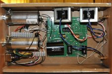
I just finished the Zen Triode kit that is modified for use with a
5U4G rectifier. See attached photos. Spent some time today finishing
and assembling it together, and ran in problems. Using all Russian
tubes. See below.
Transformer Connection
- Yellow x2 to pin 2 and 8 of 5U4G
- Red x2 to pine 4 and 6 of 5U4G
- Note connection of jumper J6. Tested continuity between all the
various GND, all connect except for the output transformers.
Test with no tubes
- Power on.
- All voltages at the transformer as expected. A little higher, but
pretty close.
1st time
- Tubes heater slowly grow - appears normal.
- See a spark and then smoke, from the the top right out put
transformer.
- Hear some clicking type noises from the output transformers.
- Turn off.
- No chance to check voltage.
2nd time
- See smoke coming from the top, not sure where
- No sparks
- Turn off.
- No chance to check voltage.
3rd time
- The 1K power resistor glowed to Red hot.
- Immediately switched off.
- No chance to check voltage.
Too scared to turn on again. Could it be a output transformer short,
cause the above issues? I am also pretty sure but had doubted if the
output tube's cathode cap was the wrong way, but I am sure it is right.
Thanks for any help you can offer, I was really looking forward to
using the amp this evening!
Second Email.
Upon further investigation, the following is noted.
Am using the supplied 3.15A 250V fuse, and they did not blow at all.
Realised that, and now will change to 1.6A 250V type.
Second, there is now an open circuit between the the left white PCB
connection of the output transformer to the ground. There is no such
continuity with the right white. The resistance of left white to gnd
is around 0.4R.
I suspect that somewhere, there is a short circuit between the left B+
supply to the ground, and thus, causing an open circuit which would
mean that all the current going through the 1K main PSU resistor is
going through the roof, and then its glowing read hot.
Therefore, if I can track down and find my short of the left white
connection and fix the fuse, this should operate as per instruction?
Should I be concerned that the 6.3V heater is sitting around 7.1V?
Third Email.
But doing some more investigation. I measure the resistance of the
right output transformer and get around 330R. I do the same for the
left (which I think has shorted or something) and it cannot lock onto
a fixed resistance. Would it be fair to say that the left output
transformer has shorter or blown, and thus causing an open circuit and
the cause of my problems?
Fourth Email
I checked again today.
J6 on the PCB, the one that connects chassis ground to shield has always been connected. This is the jumper that should've been named J7 according to the memo. Otherwise, the other J6 is also connected. So I am sure this was not the problem.
The short circuit I found at J2, I cut the jumper, and the transformer 'short' was removed, and now measures as per the other output tube. That is, both red and white wires to ground read in the megaohms.
The output transformer now tests okay when not connected.
Checked all wiring, and appears to be correct. Resistance values, connection to ground, etc.
I powered it up with no tubes, everything is as expected. 318V for each of the red leads to gnd. So I'd assume 318-0-318, rather than the 300-0-300, which is pretty close.
Powered up with just the rectifier 5U4G, and the voltage from the 1K power resistor to ground was 440V or thereabouts. No problems, no sparks, no noise. I also measure at this time, the voltage from the red and white wires of the output transformer to ground, all four read as 440V.
I put all the output tubes and input tube into the socket now and powered up. It first appears fine, the heaters all light up as they should. After about 10 or 15 seconds, I hear small sparks coming from around the two output transformers. Reasonable regular at around 2 per second. I turned off the amp immediately. I changed the output tubes and this still occured.
I am at a lost, I really want this thing to work, and it appears that everything at this moment works except when the output and input tubes are put into place. The PSU unit seems to work well. What do you think I should do to try to figure out the source of my grief? Thanks!
Attachments
- Status
- This old topic is closed. If you want to reopen this topic, contact a moderator using the "Report Post" button.