Hello everyone. Long time lurker, first time poster.
I am trying to design an amplifier with a 6Au6 pentode operating as a constant current source plate load for a medium mu triode. The equation I'm attempting to apply is in the back of Rozenblit's "Beginners Guide to Tube Audio Design":
ip = Epp - ep +mu*E)/rp+(mu+1)*R
where ip is the current through the CCS and triode, Epp is the supply voltage, E is the voltage differential between the triode's plate and the CCS's grid, mu is the gain of the CCS tube, rp is the dynamic plate resistance of the CCS tube, and R is the value of the CCS's cathode resistor.
This equation works fine when I use it for a triode loaded by a constant current source triode, but when I apply it to a pentode as the CCS (estimating at my selected operating point the 6AU6 has an rp of about 1Meg and a mu of 4,000) the equation breaks down and I start getting impossible values for R. I'm wondering if anyone could help point out where I'm going wrong? Or if there's a better way to analyze things when using a pentode as the CCS?
Hi Bitrex !
A 6AU6 is, in itself, a very good current source for a wide range of plate voltage.
In the attached graph you can see that to obtain, says 6mA you just need to bias the grid at -2 Volts and fix the screen at +150V, both relative to the cathode.
It's no so easy at it seems at first glance !
This done, the plate current will remain stable for plate voltages ranging from less than 100 to more than 400V relative to the cathode.
Beware, however, that the cathode current is the sum of the plate and the screen current wich is NOT constant.
This is usually a problem when the CCS is used to "source" current in the anode of another tube but cause no problem when used to "sink" current from a cathode.
Yves.
Attachments
Consider a Cascode of Triodes instead of a Pentode? Need not
have any screen forward biased. Same current, source or sink...
Of course, this is also an application where a depletion MOSFET
solves a lot of problems, needs no elevated heater, etc...
I have no idea which solution of these three might be least noisy.
have any screen forward biased. Same current, source or sink...
Of course, this is also an application where a depletion MOSFET
solves a lot of problems, needs no elevated heater, etc...
I have no idea which solution of these three might be least noisy.
Bitrex said:I am trying to design an amplifier with a 6Au6 pentode operating as a constant current source plate load for a medium mu triode. The equation I'm attempting to apply is in the back of Rozenblit's "Beginners Guide to Tube Audio Design":
My first preference would be to solid state that. If you still want to go with a pentode instead, I'd say fuggedabouddatequation. You'll get more accurate results from the plate characteristics.
I have a "white paper" here that describes how to make pentode based CCS's, but I can't find the thing on-line. If interested, e-mail me and I'll send it off as an attachment.
hey-Hey!!!,
I'd suggest a triode-pentode cascode. Triode on the bottom, pentode on top. I've done this with 12BY7/12HL7 with excellent results. Triode strap the bottom one as triode( or consider something like a triode like the 6C45 or strapped EF184). You'll need to create floating voltage references to allow for largest-possible R-set and to 'space' the pentode above the triode. See the Gary Pimm enhancement-mode MOSFET ccs biasing methods for ideas.
cheers,
Douglas
Thanks for all the helpful responses!
I have one further question - if I wanted to take the output of this circuit and couple it to a small power triode, for example, would it be preferable to take the output at the cathode of the pentode, or the plate of the triode? I know that the cathode of the pentode would have a lower output impedance, but it's sitting at such a high voltage that it would prevent direct coupling of the two stages. But would the plate of the triode have a low enough output impedance to drive the miller effect capacitance of a small power triode?
I have one further question - if I wanted to take the output of this circuit and couple it to a small power triode, for example, would it be preferable to take the output at the cathode of the pentode, or the plate of the triode? I know that the cathode of the pentode would have a lower output impedance, but it's sitting at such a high voltage that it would prevent direct coupling of the two stages. But would the plate of the triode have a low enough output impedance to drive the miller effect capacitance of a small power triode?
Why would the voltage at the pentode cathode be significantly higher than at the triode plate?the cathode of the pentode would have a lower output impedance, but it's sitting at such a high voltage that it would prevent direct coupling of the two stages.
I'd agree that it's better to take the output from the pentode cathode (otherwise it's a waste of a perfectlty good cf), but what does that have to do with the size of the coupling cap? That should be determined with reference to the IP impedance of the following stage, surely?Take the mu-follower output at the cathode! use a bigger coupling cap.
ray_moth said:
I'd agree that it's better to take the output from the pentode cathode (otherwise it's a waste of a perfectlty good cf), but what does that have to do with the size of the coupling cap? That should be determined with reference to the IP impedance of the following stage, surely?
I think I remember reading that there are really two sections that affect interstage low-frequency response; that there's a high pass filter created by the output impedance and the coupling capacitor in a voltage divider with the grid resistor, and then there's the grid resistor and coupling capacitor acting alone, and the cutoff goes to -12db/octave when the two response curves intersect. Maybe that has something to do with increasing the size of the coupling capacitor on the pentode cathode output? I don't know, I'd better stop now as I've begun confusing myself.
Bandersnatch said:Take the mu-follower output at the cathode! use a bigger coupling cap.
In all honesty, if you like the Triode driving Triode sound, I'd tap
the middle point of the current set resistor. This configuration is
SEPP, Triode / Anti-Triode.
It will seem like the lower triode has a virtual clone working in
parallel. Though it is actually working in Anti-Pullup. And the
drive capability seen here is exactly double what you'd have
if you tap the plate of the unassisted Triode by itself.
Or the same drive seen at the plate, but now the driven load
appears to have twice the input impedance. Same thing, only
different... You can look at this topology either way.
---------------------------------------------------
If you go all the way to the top of the current set resistor, to the
MuFollower point, low Triode's plate doesn't see the load at all.
All it sees is a constant current from the sink above. This gives
good pull up current from the top cathode, but weak constant
current pull down through the current set resistor at this tapping.
But be aware of circuits with unequal push and pull capabilities.
They often can not slew as difficult load as "output impedance"
might suggest. Or maybe they can ,but not at all frequencies of
interest.
But triode grids in A2 require higher pull up slew anyway, so if
thats the load you are driving, this imbalance in favor of pull up
might be beneficial.
kenpeter said:
...
If you go all the way to the top of the current set resistor, to the
MuFollower point, low Triode's plate doesn't see the load at all. ...
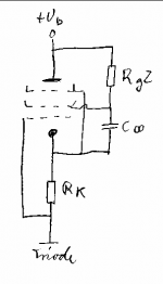
This is not true because this stage isn't a buffer. E.g. See #3 the cathode load is in parallel to Rg2 in this calculation. This reduces r.
oldeurope said:
This is not true because this stage isn't a buffer. E.g. See #3 the cathode load is in parallel to Rg2 in this calculation. This reduces r.
Im not sure we are talking about the same circuit.
Rg2 in Post#3 appears to be a screen resistor???
I think I may still get what you are driving at.
I concede that my statement was an exaggeration.
Lower plate of any Mu follower stack must see some
interaction with the load. Because the current sinking
cathode above is always imperfect (less than infinite
Gm) and therefore interacts with the load.
I merely intended to emphasise that Mu-Follower is
the least interactive tapping of the three choices
(SRPP, Anti-Triode SEPP, MuFollower) as seen from
the lower triode's plate. Which is good if you want to
track the linearity of Mu. But the most asymmetrical
in slew capability. Which could work for or against
you, depending what you are driving next.
kenpeter said:Im not sure we are talking about the same circuit.
Rg2 in Post#3 appears to be a screen resistor???
...
Yes. #3
- Status
- This old topic is closed. If you want to reopen this topic, contact a moderator using the "Report Post" button.
- Home
- Amplifiers
- Tubes / Valves
- How do I design a pentode constant current source plate load?