The thing I find both interesting and really refreshing is that this amp does so many things considered wrong by ‘experts’ and yet obviously manages to sound excellent.
Paralleled tube sections are supposed to lose detail and refinement and blur the soundstage. High resistance in the psu is considered heresy by some, and chokes are generally considered superior to high value resistors in this location. Chokes or CCS are also considered by many to make better plate loads than resistors, and LEDs or battery biasing of the cathode is often considered superior to a conventional RC network.
I guess the outcome adds some weight to the ‘it ain’t what you do, it’s the way that you do it’ philosophy of amp construction.
mach1 said:The thing I find both interesting and really refreshing is that this amp does so many things considered wrong by ‘experts’ and yet obviously manages to sound excellent.
You may be right. We don't know if it sounds excellent; it merely sounds better than other preamps which may be even more compromised and built with inferior parts. It will be very interesting if the builder explains his prefences.
The thing I find both interesting and really refreshing is that this amp does so many things considered wrong by ‘experts’ and yet obviously manages to sound excellent.
x2
Some times you just have to keep it simple and old school
hendram said:each channel tube is parareled..
each channel tube is parareled
Hi,
very nice indeed
Some questions:
Do both cathodes share the 330 Ohm Riken resistor and 470uF?
Do both anodes share the same 10K resistor!?
Kind Regards
Hauke
analog_sa said:
You may be right. We don't know if it sounds excellent; it merely sounds better than other preamps which may be even more compromised and built with inferior parts. It will be very interesting if the builder explains his prefences.
We also don't know which preamp sounded the most like the input signal.
The Spirit of DIY
Simple elegance prevails.
DT
All just for just for fun!
Hello hendram,my simple line stage E182CC preamp won in blind test tube preamp free for all event in Jakarta indonesia on Des 08.
http://jimmyauw.com/wp-content/uploads/2008/12/x_juara-sesi-1-dan-final-preamp-e182cc.jpg
Jimmy’s Junkyard Blog Archive Pre Amplifer “Free-for-All” Blind Test Session
Simple elegance prevails.
DT
All just for just for fun!
each channel tube is parareled..
each channel tube is parareled
hello guys,
i would like to build this preamp as I have all the parts needed except for the power transformer. What will be the right secindary voltage for the power transformer?
thank you...
... secindary voltage for the power transformer?...
Try 250V at around 50mA AC.
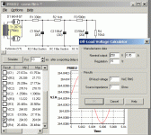
This sims-out to just about 260V of DC at the amplifiers.
Yes, the simmed rectifier is different; I have allowed for that. The single winding with diamond bridge will drop about 1V more than the double-winding 2-diode form. This double-winding is specified each-side, so same-as a single winding. It will measure 280V-290V AC NO-load, dropping to around 250V AC at full load. Voltage at the first filter cap will be near 390V DC NO-load, a bit over 300V DC under load. The 1K resistors drop this to near 260V supply to the amplifiers. I doubt it is very critical; I'd expect it to work fine 200V to 400V. (If you are facing a 27-amplifier shoot-out, you may want to try various supplies....)
Attachments
hello PRR,
I very much appreciate your response and time to model the supply. ill look up hammond and see what they have. Ill build the supply you modeled.
is there a better power supply for this preamp that is not that hard to build?
tnanks again and you are very much appreciated...
I very much appreciate your response and time to model the supply. ill look up hammond and see what they have. Ill build the supply you modeled.
is there a better power supply for this preamp that is not that hard to build?
tnanks again and you are very much appreciated...
- Status
- This old topic is closed. If you want to reopen this topic, contact a moderator using the "Report Post" button.
- Home
- Amplifiers
- Tubes / Valves
- blind test tube preamp free for all
