I have vt25 and vt25a also 10y with different brand in my tubes box .i know this tubes have nice sound and balance in all of mid and high and low.
I tray to build tube circuits and test result sound by my self . I receive to vt25 in pre amps circuit. is it possible with this power triode direct filament to build good pre amps?
")
I tray to build tube circuits and test result sound by my self . I receive to vt25 in pre amps circuit. is it possible with this power triode direct filament to build good pre amps?
You can see one nice project with 10y in this link .
http://www.vt52.com/diy/myprojects/amps/firefly/firefly.htm
http://www.vt52.com/diy/myprojects/amps/firefly/firefly.htm
An externally hosted image should be here but it was not working when we last tested it.
hooman said:You can see one nice project with 10y in this link .
http://www.vt52.com/diy/myprojects/amps/firefly/firefly.htm
An externally hosted image should be here but it was not working when we last tested it.
This is not a great circuit.
If you don't increase a lot that coupling capacitor you will have the resonance at approx. 23 Hz with a bad Q factor (poor damping)!!
Very probably you will get a floppy bass.....unless you use very small monitors.
To make it work decently you should go down to 10 Hz with a good damping, at least.
3.3uF looks much better....
Also, DC filament supply is recommendable....
Cheers,
45
This is not my idea and Jim cort has made and test this project . but tanks for your advise.
Jim cort :
I use a higher voltage on the 10Y but it biases just like I wanted... 350V/16mA... The 10Y/801A will take chokes from 150H or up to give a -1dB of a 20Hz.
and:The filament supply is done by my two battery towers which also house 12V batteries for the 26 filament. I can use these to get the 7.5V for the 10Y, no problem, only have to adjust the current regulator resistor to get the right current.so filimant ...
Gluca said:YES! But You'd better use a transformer to lower the output impedance.
Only true if trying to drive a low impedance input. The output impedance will be around 5k for this operating point. That's fine if the driven amp has an input impedance of at least 50K. Most tube amps are that or higher.
45 said:This is not a great circuit.
If you don't increase a lot that coupling capacitor you will have the resonance at approx. 23 Hz with a bad Q factor (poor damping)!!
Very probably you will get a floppy bass.....unless you use very small monitors.
To make it work decently you should go down to 10 Hz with a good damping, at least.
3.3uF looks much better....
There's nothing inherently wrong with the circuit. It's a basic parafeed amp. I don't think that damping factor is important here. The amp is driving a low, non reactive load. Just measure the response with the expected load and change the cap value if there is any peaking. Easy enough to do. Here's some related info: http://www.siteswithstyle.com/VoltSecond/Parafeed_fun/Parafeed_fun.html
Agree on the DC filament supply. You might want to try starving the filaments a bit. There is a fairly narrow range where the distortion is minimized (just below 6V for my 801 amps). Additional reading: http://greygum.net/sbench/sbench102/dht.html
http://greygum.net/sbench/sbench/heater.html
Sheldon
45 said:
This is not a great circuit
An externally hosted image should be here but it was not working when we last tested it.
If you don't increase a lot that coupling capacitor you will have the resonance at approx. 23 Hz with a bad Q factor (poor damping)!!
45
I do not see the parafeed circuit here. It looks like a simple choke loaded cap coupled to a grid resistor. Where is the resonance coming from?
dave
dave slagle said:I do not see the parafeed circuit here. It looks like a simple choke loaded cap coupled to a grid resistor. Where is the resonance coming from?
Yes, my bad for misusing the term. Can't really be parafeed in the usual sense if there is no transformer on the output. And without the transformer inductance in parallel with the cap, no resonance either, I guess. In the circuit shown, the inductor has a low Z path to common, but the cap does not, so they are not effectively parallel.
Sheldon
Thanks to for replay on my topic and I think the 10y will work prefect by transformer in matching and lode in out pot stage .but I don’t have this transformer in my box .so I should try by capacitor and specially focused on low frequency to find resonance or not !
I have 100 of vt25a they have made for western electric by hitron .these kind of tubes need to supply filament by battery for the best result in clear sound. as I told I have another kind of vt25 from uk by teonex in rebranded .the teonex vt25 is work by ac filament and I found it better in rejection the noise . I checked these two kind of tube in out put circuit in single ended before .
I have 100 of vt25a they have made for western electric by hitron .these kind of tubes need to supply filament by battery for the best result in clear sound. as I told I have another kind of vt25 from uk by teonex in rebranded .the teonex vt25 is work by ac filament and I found it better in rejection the noise . I checked these two kind of tube in out put circuit in single ended before .
Sheldon said:
Only true if trying to drive a low impedance input. The output impedance will be around 5k for this operating point. That's fine if the driven amp has an input impedance of at least 50K. Most tube amps are that or higher.
There's nothing inherently wrong with the circuit. It's a basic parafeed amp. I don't think that damping factor is important here. The amp is driving a low, non reactive load. Just measure the response with the expected load and change the cap value if there is any peaking. Easy enough to do. Here's some related info: http://www.siteswithstyle.com/VoltSecond/Parafeed_fun/Parafeed_fun.html
Sheldon
Yes it is for me. Given that load, the frequency response is ok but not the phase and above all the sound!
The inductance and the capacitor are in parallel for the signal.
Cheers,
45
Hi Hooman
I am sure that the VT25 would make a lovely low-gain stage and encourage you to go further with the project. Still it would help people around here if you tell what you want from the pre-amp: do you want it to have gain? Do you want it to have a low output impedance? What amplifier/tube will you be driving with this pre-amp?
You mentioned that you do not have the transformer. Do you have an inductor/choke? What are your options in getting either of these?
Have you already tried to use a plate resistor? The disadvantage is that you will need a quite high power supply, but that may still be easier to accomplish than getting a good transformer or choke.
Erik
45 said:The inductance and the capacitor are in parallel for the signal.
? Parallel components, by definition, must have the same terminations. That load resistor makes a big difference.
Sheldon
45 said:Given that load, the frequency response is ok but not the phase and above all the sound!
What phase problem? Frequency response and phase response are two sides of the same coin here.
Sheldon
Hi erik ,hi other my friendsErikdeBest said:Hi Hooman
I am sure that the VT25 would make a lovely low-gain stage and encourage you to go further with the project. Still it would help people around here if you tell what you want from the pre-amp: do you want it to have gain? Do you want it to have a low output impedance? What amplifier/tube will you be driving with this pre-amp?
You mentioned that you do not have the transformer. Do you have an inductor/choke? What are your options in getting either of these?
Have you already tried to use a plate resistor? The disadvantage is that you will need a quite high power supply, but that may still be easier to accomplish than getting a good transformer or choke.
Erik
Yes of curs I will make this project in next days . I don’t want much gain and I have made one power amp by 6b4g in two mono blocks ,so for volume control and some gain , I need to one good pre amp .
I can find a chock for this project and quite agree in your good points with using of transformer in tubes amplification and results . also a I start to winding some transformer and chock with good materials.
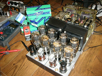
my new 6b4g amp :

Hi Hooman
That is some very nice work! I surely wouldn't be able to build in such a compact way! I did not really know your skills when I wrote my previous post, but seeing this I am sure you have more knowledge of the stuff than I do!
As you have access to transformers and chokes I would say, go for it! Impossible to tell what will be the best beforehand...
You have probably already seen this datasheet, but anyway I send you the link. It has the curves and three common operation points for the VT25, all of these for 'undistorted power output'
http://www.mif.pg.gda.pl/homepages/frank/sheets/029/1/10.pdf
I used to have a couple of these valves but had to sell them as I needed the money. Now I regret it...
Sheldon said:
? Parallel components, by definition, must have the same terminations. That load resistor makes a big difference.
Sheldon
Sheldon said:
What phase problem? Frequency response and phase response are two sides of the same coin here.
Sheldon
No, from the point of view of the signal ground and V+ terminations are the same.
In fact this happens also for the parafeed circuit you linked previously.
In that circuit the supply is in series and ideally it has zero impendance, so the load inductor is virtually grounded.
The frequency response can have no peaks because the overall RLC source resistance is high so that you are damping the peak.
The phase response, in any case, doesn't change and here you don't have many ways to "adjust" the results other than shifting the resonance at least one octave below the audio band.
45
ErikdeBest said:
I used to have a couple of these valves but had to sell them as I needed the money. Now I regret it...
So sorry for that Story .....
Thanks Erik ,but I am not so skills ,I tray to find some skills people in this job like you all my friend in these posts . , and so many problem for work with tubes here . i started with 6l6 push pull and no body can help me here .i worked and made some project like 2a3(5 months before ) - f2a(2 months before ) - 2e22(10 days …. )- el34(7 months before )-el84monts before -6l6(1 year ….)-6v6 (two times) -807(6 days before ) -6b4g (in single 8 months …..) 211 (2 moths …..)
811(2 months…..)
I love the tubes and like to buy and keep them .
45 said:No, from the point of view of the signal ground and V+ terminations are the same.
In that circuit the supply is in series and ideally it has zero impendance, so the load inductor is virtually grounded.
By that standard, everything in every circuit is in parallel as they all have a path to ground. Yes, the inductor is virtually grounded, because its path to ground is low Z. But the cap has a 470k in series to ground. I'll assume that the 470k is the termination in the pre, and that the output goes to an amp with 100k input. That still leaves about 80k in series with the cap. This is not like a classic description of a resonant circuit, where the resistance is in series with both inductor and cap. This resistance must be added to the reactance of the cap only. The resonance occurs when the reactance of both inductor and cap are the same. Now, where does that put our resonant point here? http://www.allaboutcircuits.com/vol_2/chpt_6/5.html
45 said:The frequency response can have no peaks because the overall RLC source resistance is high so that you are damping the peak.
The phase response, in any case, doesn't change and here you don't have many ways to "adjust" the results other than shifting the resonance at least one octave below the audio band.
See above. The overall source resistance is high, as is the series resistance for the capacitor return to ground. Also, the inductor will probably have significant resistance, though much lower than either source or capacitor termination resistor. Still don't see any frequency or phase problems to worry about.
Sheldon
Sheldon said:
By that standard, everything in every circuit is in parallel as they all have a path to ground. Yes, the inductor is virtually grounded, because its path to ground is low Z. But the cap has a 470k in series to ground. I'll assume that the 470k is the termination in the pre, and that the output goes to an amp with 100k input. That still leaves about 80k in series with the cap. This is not like a classic description of a resonant circuit, where the resistance is in series with both inductor and cap. This resistance must be added to the reactance of the cap only. The resonance occurs when the reactance of both inductor and cap are the same. Now, where does that put our resonant point here? http://www.allaboutcircuits.com/vol_2/chpt_6/5.html
See above. The overall source resistance is high, as is the series resistance for the capacitor return to ground. Also, the inductor will probably have significant resistance, though much lower than either source or capacitor termination resistor. Still don't see any frequency or phase problems to worry about.
Sheldon
Sheldon you gave the definition.
How much is the reactance of a resistance?
R. It is zero!!
So any resistor simply cannot change the resonance frequency which in the circuit above, for L=200H and C=0.22 uF, is 24 Hz.
It can only change the damping (energy dissipation) depending on its value and where you place it.
By definition you will have a phase rotation which extends some octaves above and below the resonance frequency.
Cheers,
45
- Status
- This old topic is closed. If you want to reopen this topic, contact a moderator using the "Report Post" button.
- Home
- Amplifiers
- Tubes / Valves
- vt25 in pre amp