Hi,
I'm a bit poor on this tube topic so please help me out.
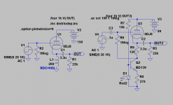
The circuit on the right (dual supply buffer) has been done before so I guess it's a working model.
My question is, can the diagram on the left using single supply be used with the same CCS?
The reason being I have the trafo and choke to provide a good 80V supply and if possible I would like to use high voltage PIO as ouput caps.
Many thanks.
I'm a bit poor on this tube topic so please help me out.
The circuit on the right (dual supply buffer) has been done before so I guess it's a working model.
My question is, can the diagram on the left using single supply be used with the same CCS?
The reason being I have the trafo and choke to provide a good 80V supply and if possible I would like to use high voltage PIO as ouput caps.
Many thanks.
Attachments
Will,
Aside from the lack of Volts, the single supply circuit will NOT work, as drawn. Where's the negative bias on the triode's grid? A DC coupled I/P is possible, only when a bipolar PSU is employed.
What are the ratings of the power trafo's rectifier winding? Depending on the rectifier winding's wiring, it may be possible to get the Volts you need, either by bridge rectification or Greinacher voltage doubling.
Aside from the lack of Volts, the single supply circuit will NOT work, as drawn. Where's the negative bias on the triode's grid?
A DC coupled I/P is possible, only when a bipolar PSU is employed.What are the ratings of the power trafo's rectifier winding? Depending on the rectifier winding's wiring, it may be possible to get the Volts you need, either by bridge rectification or Greinacher voltage doubling.
You can use -6V on the tail of CCS by using the V from heater supply. Also take out the 6.8K resistor as well, or change it to 10 ohm or 1 ohm so you can use it to measure current.
Another way is to replace all of the ccs with choke which I think will make this circuit more elegance.
Another way is to replace all of the ccs with choke which I think will make this circuit more elegance.
Eli Duttman said:Will,
Aside from the lack of Volts, the single supply circuit will NOT work, as drawn. Where's the negative bias on the triode's grid?
What are the ratings of the power trafo's rectifier winding? Depending on the rectifier winding's wiring, it may be possible to get the Volts you need, either by bridge rectification or Greinacher voltage doubling.
Thanks for the info, do excuse my lack of knowledge.
I have a 120v trafo (secondary) and when after full wave rectification will produce 120x1.4 = 168v. Hence plenty of headroom to bring voltage down. I have a 50H choke. Any suggestion?
WT said:
Another way is to replace all of the ccs with choke which I think will make this circuit more elegance.
How would you calculate the choke value? Assuming I want to bias the tube at 15mA.
revintage said:The 6922 is totally unusable if you want to make single supply CF.
Why? The ECC88/6DJ8/6922... family are great for CF's.
Hey Leadbelly,
Read the whole sentence ! It says "single supply" as in the Wills left picture. Otherwise you are right, it is really good as CF (if you happen to like CFs).
If one decide to use a input cap and lift the triodes grid from ground potential it will not be a problem to use 6DJ8.
Read the whole sentence
! It says "single supply" as in the Wills left picture. Otherwise you are right, it is really good as CF (if you happen to like CFs). If one decide to use a input cap and lift the triodes grid from ground potential it will not be a problem to use 6DJ8.
How would you calculate the choke value?
The inductive reactance (XL) at 20 Hz. should be at least 3X the triode's plate resistance. JJ's E88CC/6922 data sheet shows RP = 2.6 KOhms.
A loading choke is made differently than a PSU filter choke is made. It must perform well at freqs. > 20 KHz. OTOH, a PSU filter choke focuses on the ripple freq. and its low order overtones.
Hi Will
I would recommend to change that 6k8 value for a 470R resistor. Having a quick look at the curves a 470R resistor and 150V on the plate should bias the E88CC at about 3,5V and have 8mA running through it.
Well, in fact I would use a choke, but even better a CCS...but I think you just want something simple, and the 470R resistor will pull more current, increasing transconductance and therefore diminishing output impedance, which, I believe, makes it 'better'.
Eli Duttman said:
The inductive reactance (XL) at 20 Hz. should be at least 3X the triode's plate resistance. JJ's E88CC/6922 data sheet shows RP = 2.6 KOhms.
A loading choke is made differently than a PSU filter choke is made. It must perform well at freqs. > 20 KHz. OTOH, a PSU filter choke focuses on the ripple freq. and its low order overtones.
If I understand this correctly, with Xl=2piFL,
rearranging for
L= Xl/(2piF)
L= (3*2600ohm)/(2pi*20hz)
L= 62.06Henries
That means I'm free to use chokes greater that 62H ?
ErikdeBest said:Hi Will
I would recommend to change that 6k8 value for a 470R resistor. Having a quick look at the curves a 470R resistor and 150V on the plate should bias the E88CC at about 3,5V and have 8mA running through it.
Well, in fact I would use a choke, but even better a CCS...but I think you just want something simple, and the 470R resistor will pull more current, increasing transconductance and therefore diminishing output impedance, which, I believe, makes it 'better'.
Well in actual fact I did wanted to use a CCS with the single supply at 150V but it seems I didn't understand how to get there.
Hi Will
Yes, you are right! My post was unclear: what I meant was a CCS employing a negative rail.
For proper operation a CCS should have some voltage 'drop' across it. For example the lowly LM317 should have about 4V across it to keep acting as a CCS. That means that the voltage from the cathode to ground should be at least this drop-out voltage + half of the 'peak to peak voltage' expected at the output. Say you want a max of 2VRMS out of the buffer: the 'peak to peak voltage would be 5,6V. This voltage is 'centered' around the cathode, when the signal goes negative it will decrease by about 2,8V. At this 'valley' of the signal the voltage drop over the CCS should still be the 4V, so you can determine that the voltage at the cathode should be at least 6,8V: 4V for the CCS operation and 2,8V for the negative going signal.
An E88CC that has its grid grounded can hardly be biased with 6,8V at the cathode and therefore Revintage said they were unsuitable. Better options are valves with lower gain, as the already mentioned 6N30P, the 12B4, the 6N6P. Those can be biased with around 8V or more on the cathode, leaving enough headroom for the proper working of a CCS + signal swing.
Hope this helps, Erik
Hi Will,
Here are your two possible options if you want to stay with the 6DJ8. As the RDC of the choke defines working point this must be known.
In this case I used a Lundahl 1668 200H that is 680ohms. If you ask Jack at Electra-Print he can make you a 100H/5mA that probably will have a RDC in the ballpark of 500-700ohms.
The CCS can of course be arranged with a FET. The 6DJ8 is biased just under 5mA and both will output over 20Vrms into 22k.
Attachments
revintage said:Hi Will,
Here are your two possible options if you want to stay with the 6DJ8. As the RDC of the choke defines working point this must be known.
In this case I used a Lundahl 1668 200H that is 680ohms. If you ask Jack at Electra-Print he can make you a 100H/5mA that probably will have a RDC in the ballpark of 500-700ohms.
The CCS can of course be arranged with a FET. The 6DJ8 is biased just under 5mA and both will output over 20Vrms into 22k.
Many thanks, I like the choke version; simple and elegant ! Furthermore since I already have 150V supply it's a no brainer.
As for the choke RDC of 680 ohm do you mean it's a matter of having 680ohm across the choke when measured with an ohm meter?
revintage said:Will,
You are completely right about measuring with your ohm-meter.
The inductance is not critical when using it in a CF. A 100H corresponds to ca 13k at 20Hz. As Zout from the CF is low you can even get away with a cheap psu choke like 157G(30H/595ohm) from Hammond.
I see thanks. That was helpful.
But wow, if I wanted to build a 6 channel tube buffer with the chokes its not going to be space and cost effective I reckon. That Hammond is $25 each.
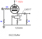
Saw this concept from Tubecad that the LM317 can be used, to set at 10mA bias, simply use 1.24/Iq = 124ohm resistor. Since I have 120ohm resistor and LM317, will this also work?
Attachments
- Status
- This old topic is closed. If you want to reopen this topic, contact a moderator using the "Report Post" button.
- Home
- Amplifiers
- Tubes / Valves
- Single supply 6922 buffer with 2SK CCS