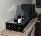
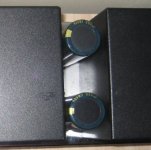
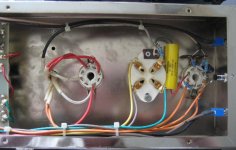
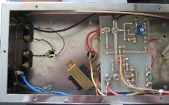
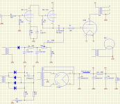
Just bought a couple of 2nd hand 300B mono amps and I had a closer look inside the units and came up with the attached diagram.
My question is if anyone can help me with determining, based on the diagram, how to measure and adjust the bias? (I assume the variable resistor in diagram is for grid bias, correct me if I am wrong).
While I do have some knowledge of electronics in general, my knowledge of tube amplifier designs is very limited.
Btw: is it safe to run 300B tubes upside down while adjusting? (the variable resistor is only accessible from the bottom)
Cheers
Attachments
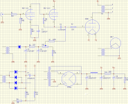
Before anything else, there are some real issues with the design. The 5V4 is rated for a 10uF input cap -- this design uses a 680uF. If nothing else, this is going to cause you to replace those rectifier tubes pretty quickly. Second, the 6SL7 can't push a 300B.
To answer your question, you measure the bias from the grid to the cathode. Where you want it will depend upon what B+ is, but there are no numbers on the schematic so it is hard to say. But, the Western Electric 300B datasheet gives lots of reasonable operating points.
To answer your question, you measure the bias from the grid to the cathode. Where you want it will depend upon what B+ is, but there are no numbers on the schematic so it is hard to say. But, the Western Electric 300B datasheet gives lots of reasonable operating points.
For bias adjustment it may be most convenient to measure the current, by connecting the voltmeter over the cathode resistor. Example; 0.65V across the 13 ohm resistor to GND will correspond to 50mA.
While it may not be the most ideal driver for 300B, it is not the first time we have seen 6SL7 SRRP as input/driver.
Attached is a table of alternative 300B operating conditions.
SveinB.
While it may not be the most ideal driver for 300B, it is not the first time we have seen 6SL7 SRRP as input/driver.
Attached is a table of alternative 300B operating conditions.
SveinB.
Attachments
The 5V4 is rated for a 10uF input cap -- this design uses a 680uF. If nothing else, this is going to cause you to replace those rectifier tubes pretty quickly.
Thanks, that is great advise. I was wondering about that when I compared to other 300B SET diagrams, the caps in this one seem very large. Would it be enough to just replace the first 680uF (C6 in the schematic) with a 10uF? or do you recommend I also reduce the second one after the inductor with a smaller value e.g. 50uf?
Replacing the 6SL7 with something more appropriate will require a lot more changes I guess.
Cheers
Attachments
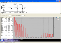
Probably the best thing to do is use PSUD to model a power supply. You might be able to insert some extra resistance before the first filter cap, or before the plates of the rectifier, or both. If this drops too many volts, a different rectifier (or even some solid state diodes) might help. Smaller caps might also be good. Lots of options, but the simulator will be useful.
as for the 6SL7, while still not ideal, a 6SN7 is much better. You will lose gain, so if you need that then it isn't such a good option. There are also octal 6H30's that might work, but again gain is an issue.
You can also use an adapter to drop in 9-pin tubes which opens up lots of high gain high Gm drivers that should work.
More complicated, some sort of mosfet follower can likely be dropped in -- see tubelab.com
Finally, as was noted, lots of pepole listen to 6SL7-300B amps and are perfectly happy. So, if you like the amps, you can simply not worry about it")
as for the 6SL7, while still not ideal, a 6SN7 is much better. You will lose gain, so if you need that then it isn't such a good option. There are also octal 6H30's that might work, but again gain is an issue.
You can also use an adapter to drop in 9-pin tubes which opens up lots of high gain high Gm drivers that should work.
More complicated, some sort of mosfet follower can likely be dropped in -- see tubelab.com
Finally, as was noted, lots of pepole listen to 6SL7-300B amps and are perfectly happy. So, if you like the amps, you can simply not worry about it
A few comments:
1- Check you wiring on the 5V4G rectifier... this is an indirectly-heated cathode full-wave rectifier. The Cathode is tied to pin 8 of the socket. This is where you should get your B+ from, not pin 2.
2- You could easily reconfigure the input/driver stage so the first stage of the 6SL7 is a gain stage directly coupled to the grid of the second stage which could be configured as a cathode-follower. You would have less overall gain but the output impedance driving the 300B would be lower. Personally, I don't like SRPP stages, just my $0.02.
3- As this is a fixed bias design, I would suggest placing a filter cap from the wiper of the bias pot to ground. As it is now, your grid load impedance changes as you adjust the bias pot.
Regards, KM
One last comment.... your filter caps in the bias supply are drawn reverse polarity, at least I hope so... as it's a negative bias supply, the positive end goes to ground. Per my comment above, you could simply move C4 from the end of the bias pot to the wiper of the bias pot.
Regards, KM
Regards, KM
For bias adjustment it may be most convenient to measure the current, by connecting the voltmeter over the cathode resistor. Example; 0.65V across the 13 ohm resistor to GND will correspond to 50mA.
Thanks, I will try make some basic measurements over the weekend and post the results.
Is it enough to just measure the voltage over the last 13 ohm resistor to ground (R11 in the schematic), or should I include the other 13 ohm resistors (R9 or R10) ?
Cheers
dsavitsk said:Probably the best thing to do is use PSUD to model a power supply. You might be able to insert some extra resistance before the first filter cap, or before the plates of the rectifier, or both. If this drops too many volts, a different rectifier (or even some solid state diodes) might help. Smaller caps might also be good. Lots of options, but the simulator will be useful.
That is a very cool simulator, and indeed, as you predicted it, it gives a warning that the current is too great during startup. (see attachment, this is even without adding the load)
Could I simply just disconnect the first 680uF cap (C6) in the PSU?
as for the 6SL7, while still not ideal, a 6SN7 is much better. You will lose gain, so if you need that then it isn't such a good option. There are also octal 6H30's that might work, but again gain is an issue.
Are 6SN7 and 6SL7 so much compatible, that I could just replace the existing 6SL7 tube with a 6SN7 to see if I like it better? Or would I need to modify resistor values to make it work?
Finally, as was noted, lots of pepole listen to 6SL7-300B amps and are perfectly happy. So, if you like the amps, you can simply not worry about it
They don't sound bad at all, but the sound is probably a little too polite. I am a firm believer in proper circuit designs and a bit of tweaking here and there (or perhaps a rebuild) is for me a big part of the fun of this hobby
Attachments
kmaier said:A few comments:
1- Check you wiring on the 5V4G rectifier... this is an indirectly-heated cathode full-wave rectifier. The Cathode is tied to pin 8 of the socket. This is where you should get your B+ from, not pin 2.
....
One last comment.... your filter caps in the bias supply are drawn reverse polarity, at least I hope so... as it's a negative bias supply, the positive end goes to ground.
....
Thanks, well spotted, those are mistakes in my schematic. I have corrected it. See attachment.
Cheers
Attachments
- Status
- This old topic is closed. If you want to reopen this topic, contact a moderator using the "Report Post" button.
- Home
- Amplifiers
- Tubes / Valves
- 300B SET Bias Help