OK. I've lurked in the shadows here for about a week. Searching as best I could for as long as my eyes and brain could take on a daily basis. I've found a lot of information, now I need help using it.
I purchased a set of ASL Wave 8 mono-blocks used off of A'gon. It was sort of thought out. I had read several promising reviews that these were the perfect tube amp for someone wanting to get their feet wet with tubes for the first time without spending any serious cash. Not completely unlike myself.
I had been evolving my system over a period that spanned about a year and a half. I started with an old SS Denon integrated amp with only my old Rotel 855 CD player and the KEF 104/2s that I discovered abandoned in a repair shop 10 years ago.
My current system still has the Rotel, but it plays second fiddle to my VPI HW19 turntable which is fed into an Audible Illusions Modulus 2D and then amplified by a Counterpoint SA-12 hybrid amplifier. The KEFs are still in place. I realize the KEFs are not anywhere near ideal for use with the little Waves, but I thought I could get an idea of what the ASLs were capable of with them due to their reasonable 92dB sensitivity . My intention in the future is to build a set of speakers using a Planet HiFi design for some Fostex 206Es that I picked up.
This new system gave me a taste of tubes and started me searching for a simple tube amplifier. I mention all this only as a way of trying to establish a reference for the problem I have concerning the ASL Wave 8 amps. That problem is simply...noise. I can't get past the noise they make and enjoy the music.
Since the first time I tried hooking the ASLs up in my system there has been very audible humming and also some buzzing coming from the amps. I had become aware of a very slight increase in hum when I had integrated the Counterpoint hybrid and the Modulus 2D into the system, but the improvement in sound quality had been enormous and the slight hum was very easily dismissed.
I thought to myself first that I have no experience with a true all tube amplification system. Shouldn't there be more noise? But how much? What should it sound like? Also, how much could I really expect from these cheap little amps?
I have no true electronics expertise, except what I've gained from working on cars for a living having to diagnose various electrical problems. I decided to try and isolate the noise in whatever way I could think. I tried switching the amps to different channels. Swapping the tubes from one amp to the other. Running the amps with no input signal at all. Swapping in a different set of tubes that came with them (the different set of tubes may have had a slightly lower level of noise, but it was difficult to say for sure due to the lapse in time between listening). I noted that each amplifier seemed to have a different frequency and nature to the noise coming from it. One seemed to buzz at a low frequency, the other hummed in a higher range which had been more noticeable to me at first. The noises migrated with the amps when I tried swapping them on channels and remained the same with no input signal. No matter what I did the noise did not go away, and actually at one point I believed that it may have become worse.
I have since come to suspect that increase in noise I thought I heard may have been due to the fact that the furnace was cycling in my house and was contributing to the noise. I only have surge suppressing power strips for my system and no true power conditioning in my 60 year old house that didn't even have grounded outlets until I installed self grounding replacements myself.
The life and condition of the tubes that came with the amps is an unknown. I have followed several strings and links on here and read that certain tubes seem to create more noise than others in these amps. The tubes that came with the amps were a set of Ei ECL 82 tubes and a set of Matsushita 6BM8 tubes. The Matsushita tubes are the ones I thought created less noise, however, the noise remained even though it was slightly subdued and it still had its corresponding buzzing or humming in each amp. I have found some fairly inexpensive replacement tubes by Electro Harmonix and Sovtek on line, but I am not sure if that is where I really need to start to address this issue.
I have read an enormous amount about these amps in the last week. I downloaded the schematic and tried to familiarize myself with it. I've read about bypassing and replacing capacitors and resistors. Using different tubes and power cords. Rotating transformers and on and on. It sounds like there are people who have been very enthusiastic about these amps and that they could be made to sound wonderful. I'd like to get to that point. If you have any advice, I'd appreciate it.
Perhaps the cheap Chinese PSU 'lytics need replacement.
Check for ground loops, which are an all to common problem.
Perhaps your AC mains are contaminated with DC "nasties". A DIY DC blocker made from a pair of SS diodes and some large value caps. has been posted on the WW web.
Check for ground loops, which are an all to common problem.
Perhaps your AC mains are contaminated with DC "nasties". A DIY DC blocker made from a pair of SS diodes and some large value caps. has been posted on the WW web.
Thanks for the advice. The ground loop issue had been mentioned to me before. Its been hard to focus lately with a 5 month old in the house. I had forgotten that I had added a second power strip from a different source to the system when I hung a new case for all my equipment on the wall several months back. It seems that this was the source of the increase in noise and buzzing I noticed. I was able to isolate that noise and was able to get rid of a ground loop through the interconnect cables by feeding both strips from the same outlet.
One of the ASL amplifiers seems to be just about as quite as my Counterpoint hybrid now. Unfortunately, the other one still has the very pronounced and distracting humming noise coming from it.
I took advantage of the situation by confirming again that the hum had nothing to do with my source or tubes by disconnecting the interconnects and trying the tubes from the quiet amp in the humming one. I also swapped the power cords and speaker cables to make sure it wasn't a problem in them. No dice, the noise doesn't go away and migrates with the amp.
At least things have improved slightly, and I think I can assume that the condition of the tubes is irrelevant at this point and that the noise is elsewhere in the circuit of the noisy amp.
I guess the next best thing I can think of is to open up the noisy amp and visually inspect it for any obvious bad connections.
I have literally resorted to going out and buying Cicuitbuilding for Dummies to help myself with this. It has a few chapters on diagnostics and I really just want to learn more. If anyone else has some more input... I'm listening. Thanks again.
OK... I spent some time looking inside my humming ASL Wave amp while looking at a schematic for it. I actually had two schematics that varied slightly in specifications. I've linked the more legible of the two below in hopes that someone with electronics expertise might refer to it if needed to help me with the observations I've made concerning these amps. The only real difference I noted in the schematics was in the value specified for two of the capacitors that just happens to be the focus of my questions and also the most common modification for these amps.
Stock Wave Schematic
I've also inserted a few pictures. The first is of both amps opened up and compared side by side:
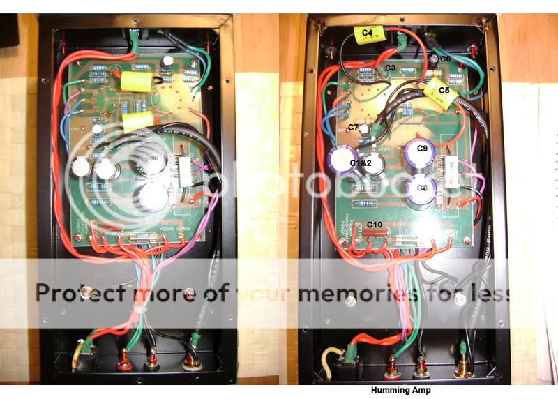
When I first opened the humming amp I didn't know where to look. As I said in my previous post, I had isolated the problem of the noise to definitely be coming from the amp itself. My first observations were that there seemed to be a slightly loose binding terminal at the chassis and that the wires for the power switch were laying on top of the C3 capacitor. I looked for loose wires and couldn't find any. I tightened the post and shifted the wire and tested the amp again. No dice, it still hummed.
When I reopened the amp to look at it a second time, the first thing I noticed was the large yellow capacitors that were mounted on very long leads to the board. I would never have guessed that when I took a closer look I would see that they were labeled Auricap and were the .47uf caps that I had read so much about as being the best upgrade for these amps (I had been given very little information about the amps when I purchased them). I thought that was good news. Then I thought it might not be so good, as it just confirmed that someone else had already had the amps open and was messing around in there.
I then decided to open the other amp that was working quietly for comparison. When I did I noticed several different things. It seemed like different size capacitors had been used in the same locations on the two different amps. I scratched my head and looked at the schematic. After a while I was able to discern with pretty good certainty which caps were which (as labeled in the pic, correct me though please if I am wrong).
It seemed as if the two amps had different caps being used in both the C9 and one of C1/C2 positions ( I wasn't able to confirm which of the C1/C2 caps as my abilities to decipher the schematic and compare it to the board are limited). I assumed which cap was the C9 with more certainty because it was the only cap that was supposed to have a 100uf 450v specification. That particular size cap was installed in only the amp that was working quietly in the position that I was able to narrow down to being either C8 or C9 from the schematic. The humming amp has a 47uf 450v cap installed in the same location. I'm not sure what affect this could have on that amp.
The swap that was done on the C1&C2 cap that I mentioned is in the quiet amp, although in this case the specification had been upped from the called for 22uf 450v to a 47uf 450v capacitor. I found this difference in components all kind of disturbing and didn't know what to make of it. I looked at the serial numbers on the amps and found that they weren't even close to one another. I guessed they might be throwing in whatever is lying around the factory in China that will work when it comes to building these things (hence the price). I'm wondering if I should make any effort to replace the caps that don't appear to match specifications on the schematic?
I also noticed some differences in the size and color coding of some resistors from one amp to the other at the R5, R14 and R15 positions. Since I can't decipher the color coding as of yet, I don't know what to think.
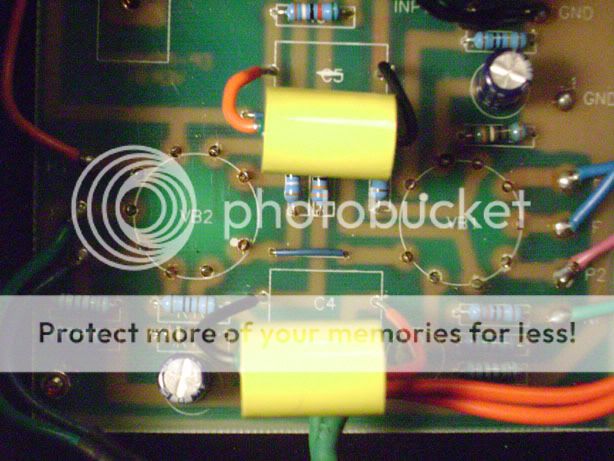
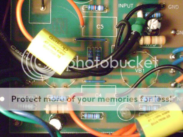
I think the most important discovery I made relates to the Auricaps. After comparing the amps for a while, I noticed that the polarity of the Auricaps that had been installed in the C4 position of both amps differed from one to the other. I know they have a certain polarity, and there was even mention of the polarity issue in a post I found on AA. But the picture that was linked to the post that was supposed to demonstrate the proper installation and polarity was dead. I couldn't find any other information on their proper installation. I don't want to just assume what is correct. I think whoever installed them screwed up in some way, because only one of the amps should be correct. For all I know, they could all be installed incorrectly. I could assume the quiet one to be OK, but I think that would be wrong of me to do. I also don't know if just reversing the polarity of the Auricap in the humming amp to match the quiet one would solve the problem. Perhaps the cap in question is damaged if it is installed incorrectly? Below are some close up pics of the installed Auricaps.
The quiet Amp:
The humming Amp:
If you have any insight as to how I should proceed I sure would appreciate your input. Thanks.
Stock Wave Schematic
I've also inserted a few pictures. The first is of both amps opened up and compared side by side:
When I first opened the humming amp I didn't know where to look. As I said in my previous post, I had isolated the problem of the noise to definitely be coming from the amp itself. My first observations were that there seemed to be a slightly loose binding terminal at the chassis and that the wires for the power switch were laying on top of the C3 capacitor. I looked for loose wires and couldn't find any. I tightened the post and shifted the wire and tested the amp again. No dice, it still hummed.
When I reopened the amp to look at it a second time, the first thing I noticed was the large yellow capacitors that were mounted on very long leads to the board. I would never have guessed that when I took a closer look I would see that they were labeled Auricap and were the .47uf caps that I had read so much about as being the best upgrade for these amps (I had been given very little information about the amps when I purchased them). I thought that was good news. Then I thought it might not be so good, as it just confirmed that someone else had already had the amps open and was messing around in there.
I then decided to open the other amp that was working quietly for comparison. When I did I noticed several different things. It seemed like different size capacitors had been used in the same locations on the two different amps. I scratched my head and looked at the schematic. After a while I was able to discern with pretty good certainty which caps were which (as labeled in the pic, correct me though please if I am wrong).
It seemed as if the two amps had different caps being used in both the C9 and one of C1/C2 positions ( I wasn't able to confirm which of the C1/C2 caps as my abilities to decipher the schematic and compare it to the board are limited). I assumed which cap was the C9 with more certainty because it was the only cap that was supposed to have a 100uf 450v specification. That particular size cap was installed in only the amp that was working quietly in the position that I was able to narrow down to being either C8 or C9 from the schematic. The humming amp has a 47uf 450v cap installed in the same location. I'm not sure what affect this could have on that amp.
The swap that was done on the C1&C2 cap that I mentioned is in the quiet amp, although in this case the specification had been upped from the called for 22uf 450v to a 47uf 450v capacitor. I found this difference in components all kind of disturbing and didn't know what to make of it. I looked at the serial numbers on the amps and found that they weren't even close to one another. I guessed they might be throwing in whatever is lying around the factory in China that will work when it comes to building these things (hence the price). I'm wondering if I should make any effort to replace the caps that don't appear to match specifications on the schematic?
I also noticed some differences in the size and color coding of some resistors from one amp to the other at the R5, R14 and R15 positions. Since I can't decipher the color coding as of yet, I don't know what to think.
I think the most important discovery I made relates to the Auricaps. After comparing the amps for a while, I noticed that the polarity of the Auricaps that had been installed in the C4 position of both amps differed from one to the other. I know they have a certain polarity, and there was even mention of the polarity issue in a post I found on AA. But the picture that was linked to the post that was supposed to demonstrate the proper installation and polarity was dead. I couldn't find any other information on their proper installation. I don't want to just assume what is correct. I think whoever installed them screwed up in some way, because only one of the amps should be correct. For all I know, they could all be installed incorrectly. I could assume the quiet one to be OK, but I think that would be wrong of me to do. I also don't know if just reversing the polarity of the Auricap in the humming amp to match the quiet one would solve the problem. Perhaps the cap in question is damaged if it is installed incorrectly? Below are some close up pics of the installed Auricaps.
The quiet Amp:
The humming Amp:
If you have any insight as to how I should proceed I sure would appreciate your input. Thanks.
I decided to try reversing the polarity of the one Auricap in question.
It made no difference at all, the amp is still humming away.
I am wondering even more now what to do about the Auricaps as I have no guide to the proper polarity for their installation. After searching for days all that came up was the one dead link on AA.

Any Help?
It made no difference at all, the amp is still humming away.
I am wondering even more now what to do about the Auricaps as I have no guide to the proper polarity for their installation. After searching for days all that came up was the one dead link on AA.
Any Help?
It looks from your picture that C8 and C9 are the original caps in the amp that has noise and the quiet amp has had a replacement cap in the C9 slot. These would be your two power supply caps C9 100/450 and C8 47/450. I would replace these in the amp with noise and shorten the leads up on the coupling caps.
chromenuts said:When I first opened the humming amp I didn't know where to look. As I said in my previous post, I had isolated the problem of the noise to definitely be coming from the amp itself.
Are you saying the humming noise is coming directly from the amplifier itself, or is it coming out the speaker connected to that amp?
Power transformers are known to generate humming or buzzing noises. In many cases there isn't a whole lot you can do about it. If there are bolts going through the lamination holding the transformer together, make sure the nuts are snug. Mounting the transformer on elastic bushings to mechanically isolate it from the chassis can help treat the symptom, but doesn't really cure the problem. Humming power transformers are sometimes better or worse depending on the quality of the AC power in the home. Try moving the power cord to a different circuit, or try it at someone else's home. I've also heard some people report improvements by wedging small shims between the core and the bobbin in cases where the bobbin was a little loose. The last remedy is to get the specs on the power transformer and replace it with a higher quality unit.
Hi There
I'm a 'tube newbie' myself so I would get a few more opinions before you do what I'm about to suggest (cannot be held responsible etc..) BUT
They are monoblocs, you have a preamp, yes? Try 'lifting' the ground on them by putting in a cheap 47 ohm resistor 'through' each earth as it enters each amp.
I suggest this as it cured my source of humming with my (home made) monoblocs...
burnedfingers said:It looks from your picture that C8 and C9 are the original caps in the amp that has noise and the quiet amp has had a replacement cap in the C9 slot. These would be your two power supply caps C9 100/450 and C8 47/450. I would replace these in the amp with noise and shorten the leads up on the coupling caps.
I could not speculate as to what might have been replaced or not, the solder joints under the boards don't tell me anything except where the Auricaps had been installed. I can say that the the large black cap in the quiet amp is of the correct specification, and I also did note the incorrectly specified 47uF cap in the #9 position on the noisy amp. I am considering swapping it out, however I am trying to keep this simple and am still checking grounding points and trying to get a better look at all the soldering joints on the board. The leads on the Auricap are sloppy that's for sure.
Ty_Bower said:
Are you saying the humming noise is coming directly from the amplifier itself, or is it coming out the speaker connected to that amp?
The humming noise comes through the speaker when the amp is connected to it.
tmhajw said:Hi There
I'm a 'tube newbie' myself so I would get a few more opinions before you do what I'm about to suggest (cannot be held responsible etc..) BUT
They are monoblocs, you have a preamp, yes? Try 'lifting' the ground on them by putting in a cheap 47 ohm resistor 'through' each earth as it enters each amp.
I suggest this as it cured my source of humming with my (home made) monoblocs...
Thanks for the suggestion...I am taking notes. I'm wondering if this is a way to address the fact that I may still have some type of ground loop in the amp?
Thanks for all the feedback I appreciate it. I just wanted to also mention that I am looking for some locals to network with that might have a club or the like where I can learn more from fellow tube enthusiasts. I tend to learn better in hands on situations or by observing rather than reading in books. Let me know if there's anyone in the CT area.
If it turns out not to be a ground loop, I wonder if it is residual hum coming off the power supply. I'm guessing there is about 1.15 volts of residual 120 Hz ripple on the B+. It'll mostly cancel out in the push/pull finals, and the front end looks like it has the supply reasonably well decoupled. How sensitive are your speakers?
From the looks of the board, you ought to be able to cut out R17 (the 100 ohm, 3w cemented resistor) without too much trouble. Replace it with a small cheap choke, like the Triad C-24X. It ought to reduce the 120 Hz ripple by nearly a factor of seven.
From the looks of the board, you ought to be able to cut out R17 (the 100 ohm, 3w cemented resistor) without too much trouble. Replace it with a small cheap choke, like the Triad C-24X. It ought to reduce the 120 Hz ripple by nearly a factor of seven.
chromenuts said:It seemed as if the two amps had different caps being used in both the C9 and one of C1/C2 positions ( I wasn't able to confirm which of the C1/C2 caps as my abilities to decipher the schematic and compare it to the board are limited). I assumed which cap was the C9 with more certainty because it was the only cap that was supposed to have a 100uf 450v specification. That particular size cap was installed in only the amp that was working quietly in the position that I was able to narrow down to being either C8 or C9 from the schematic. The humming amp has a 47uf 450v cap installed in the same location. I'm not sure what affect this could have on that amp.
The swap that was done on the C1&C2 cap that I mentioned is in the quiet amp, although in this case the specification had been upped from the called for 22uf 450v to a 47uf 450v capacitor.
Using a 47uF cap at C9 (instead of the 100uF as shown on the schematic) will produce twice as much 120 Hz ripple on the B+ rail. This is undesirable - I'd suggest you replace C9 with the correct value cap, or maybe even a 120uF. The 450 volt rating on this cap is nice, but almost certainly not necessary. You won't ever see more than 300 volts DC out of that supply (transformer rating 210VAC times 1.414). I'd be tempted to use a 400 volt rated cap because they are smaller and less expensive. The Panasonic TS-UP series caps can be bought online from DigiKey. They come in a variety of sizes from tall/thin to short/fat. Maybe look at the P6143-ND or the P7415-ND. Check your circuit board to see what size will fit, and check the datasheet to see what sizes are available.
Using a larger cap at C1 or C2 (47uF instead of the 22uF shown on the schematic) would usually be a good thing. It should provide better filtering to the sensitive front end of the amp. On the other hand, if it is a poor quality cap(leaking DC) maybe it's making the problem worse. Or perhaps the original owner tried increasing that cap in an attempt to address the humming issue. Who knows? I might be tempted to order a replacement anyway, since you will likely be ordering a cap for C9. You can try sticking an ohmmeter across the leads for C1 and C2 while the amp is powered off and unplugged. You want to see a nice big DC resistance here - at least 100k ohms or more. I find it's easier to check this with an analog meter, since the cap will appear to be low ohms at first. Then the ohms will climb slowly as the cap charges up. Give it a minute or two before you take your final reading.
Ty_Bower said:If it turns out not to be a ground loop, I wonder if it is residual hum coming off the power supply. I'm guessing there is about 1.15 volts of residual 120 Hz ripple on the B+. It'll mostly cancel out in the push/pull finals, and the front end looks like it has the supply reasonably well decoupled. How sensitive are your speakers?
Speakers have 92dB sensitivity and a 4 Ohm load.
From the looks of the board, you ought to be able to cut out R17 (the 100 ohm, 3w cemented resistor) without too much trouble. Replace it with a small cheap choke, like the Triad C-24X. It ought to reduce the 120 Hz ripple by nearly a factor of seven.
Interesting...I wish I already understood more about the circuitry and how this affects it. It sounds a little aggressive for me to try right now, and there seems to be more obvious things that are wrong to begin with, but I will keep this in mind...thanks.
Ty_Bower said:
Using a 47uF cap at C9 (instead of the 100uF as shown on the schematic) will produce twice as much 120 Hz ripple on the B+ rail. This is undesirable - I'd suggest you replace C9 with the correct value cap, or maybe even a 120uF. The 450 volt rating on this cap is nice, but almost certainly not necessary. You won't ever see more than 300 volts DC out of that supply (transformer rating 210VAC times 1.414). I'd be tempted to use a 400 volt rated cap because they are smaller and less expensive. The Panasonic TS-UP series caps can be bought online from DigiKey. They come in a variety of sizes from tall/thin to short/fat. Maybe look at the P6143-ND or the P7415-ND. Check your circuit board to see what size will fit, and check the datasheet to see what sizes are available.
OK...this definitely is on the list of things to do...along with changing out any other incorrect components. Pretty simple, the specs call for it and its not there. Its good to read an explanation about how the change affects the circuit. I had looked into Parts Express as I have ordered from them before. They have the exact spec'd cap by Xicom for $5...no datasheet on their site though. Any preference for the Pansonic caps or the Xicoms?...or is it six for one, a half dozen the other? Also, do the dimensions of the leads and their spacing usually change along with the overall cap dimensions as they vary?...or are they standardized?
Using a larger cap at C1 or C2 (47uF instead of the 22uF shown on the schematic) would usually be a good thing. It should provide better filtering to the sensitive front end of the amp. On the other hand, if it is a poor quality cap(leaking DC) maybe it's making the problem worse. Or perhaps the original owner tried increasing that cap in an attempt to address the humming issue. Who knows? I might be tempted to order a replacement anyway, since you will likely be ordering a cap for C9. You can try sticking an ohmmeter across the leads for C1 and C2 while the amp is powered off and unplugged. You want to see a nice big DC resistance here - at least 100k ohms or more. I find it's easier to check this with an analog meter, since the cap will appear to be low ohms at first. Then the ohms will climb slowly as the cap charges up. Give it a minute or two before you take your final reading.
Noted...they are cheap...maybe I'll swap them all out for the 47uF caps. I also need something like a 1k 10 watt resistor to drain the caps according to a local so that its safe to work on these.
I still need to find a way to check for the proper polarity on the Auricaps that are already installed.
chromenuts said:I still need to find a way to check for the proper polarity on the Auricaps that are already installed.
These capacitors are not polarized. The black lead indicates the outer foil. For absolute minimum noise pickup, it would typically get connected as the "input" to the cap. See paragraph five here. Also some reading here.
On your amp the black leads would be connected towards V2A. The red leads would go towards R10 and R11. For all practical purposes, I doubt it makes much difference which way they are installed. I wouldn't worry about switching them around, but feel free to do so if it makes you feel better.
Ty_Bower said:
These capacitors are not polarized. The black lead indicates the outer foil. For absolute minimum noise pickup, it would typically get connected as the "input" to the cap. See paragraph five here. Also some reading here.
On your amp the black leads would be connected towards V2A. The red leads would go towards R10 and R11. For all practical purposes, I doubt it makes much difference which way they are installed. I wouldn't worry about switching them around, but feel free to do so if it makes you feel better.
Sorry...this was a misuse of terminology...and just my way of expressing that I understood that the orientation of the leads was important to optimal installation. I had actually already read the information in those links, which is why I was preoccupied with the installation of these caps. My problem lay in the fact that I did not understand the circuit and how the caps should be installed, which you were kind enough to explain below. Thank you, yet again.
Have you rule in or rule possible ground loop? If not, I will short the input of the block that is at fault and connect only this block to the speaker. If it still hums, then you know the fault is within this block and can focus on how to trouble shoot. Eli's suggestion of DC blocker is also an easy and cheap way to eliminate another potential cause.
Update:
I finally got some replacement caps in that I ordered from Digi. I replaced the C9 cap in the humming amp with a proper spec 100uF 450v Panasonic cap. I also had to re-solder the lead from the RCA jack on that amp, as the wire snapped off due to flipping the board in and out of the amp chassis so many times while I've been working on it. I also found a sloppy soldering job on one of the Auricaps.
Unfortunately, my humming is not gone. I'm pretty disappointed to say the least. I feel like I'm stabbing in the dark here now. I actually purchased enough caps to replace most of them in both amps if need be. I don't see the point if I don't have the ability to perform any diagnostics that would indicate that course of action. Any suggestions?
From the sound of it you have a ground loop. If this is the case (and it most probably is) then changing caps and polarity of coupling caps is going to make sod all difference. You need to find the source of the loop. There have been some suggestions above regarding trying to isolate from other equipment by shorting out inputs and then reporting back...
chrish said:From the sound of it you have a ground loop. If this is the case (and it most probably is) then changing caps and polarity of coupling caps is going to make sod all difference. You need to find the source of the loop. There have been some suggestions above regarding trying to isolate from other equipment by shorting out inputs and then reporting back...
There is no other equipment connected to the amp. It is simply plugged in and connected to the speaker. When powered up, it hums.
So far the cap that was replaced was changed because it didn't meet specification, and there was speculation as to that being a possible reason for the humming.
If someone could explain to me the proper way to "lift the ground" and/or "short the input" I would appreciate it.
As I understand it, lifting the earth in your monoblocs will encourage the signal grounds to flow back to your preamp, as they should.
The simplest way to do this is to locate your earth wire on the immediate inside end of your power supply socket, cut it & insert a 47 ohm resistor. This should incidentally present little problem for chassis earthing should any catastrophe occur & it ever go live.
Try it and see. You can easily reverse it....
Thomas
- Status
- This old topic is closed. If you want to reopen this topic, contact a moderator using the "Report Post" button.
- Home
- Amplifiers
- Tubes / Valves
- Newbie and ASL Wave 8 problems