An externally hosted image should be here but it was not working when we last tested it.
An externally hosted image should be here but it was not working when we last tested it.
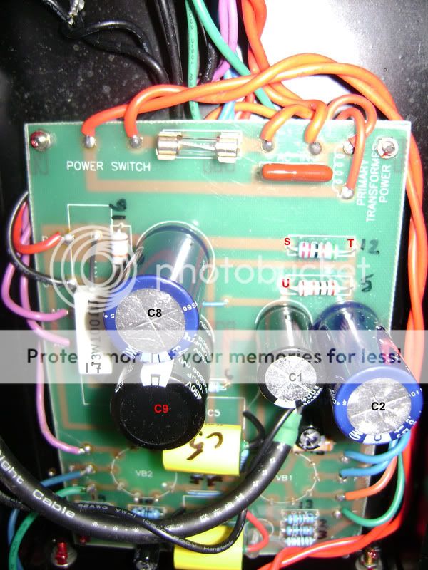
Thanks Ty. That was an absolute gift. I was trying to come up with a way to show you guys visually where I was taking the measurements on the PCB and reference them to the schematic. That worked perfectly. I will continue the method for some of the other measurements related to the power supply and etc. that are on the schematic. I"ll just provide another pic of the PCB lettered with another chart of data.
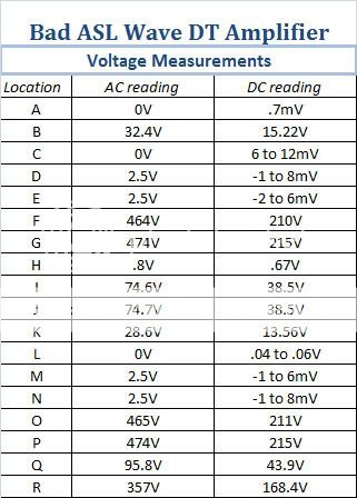
For now, you can see I managed to take the measurements that you mapped out for me on the Bad amp only. I got kind of tired and didn't want to make any dumb mistakes around high voltage. Hope to have the data from the other amp, and additional soon. Thanks again.
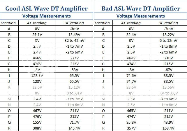
I thought I was going to be able to just edit my last post and add this new info...no dice. So here is the second chart with all the pin voltage measurements in AC and DC for the ASL Wave that appears to be working well. I also put in the first chart, lettered pic and schematic so they can be compared side by side easily.
There are some pretty substantial differences between the two amps. Hopefully that will help target problems in the circuit. I don't have the ability to comment on them, so I'll leave it up to you guys at this point. I can and will take other measurements, just need to take some pics and Pshop them so you can see what I'm talking about.
Hopefully this will give some insight so that some progress can be made. Thanks.
There are some pretty substantial differences between the two amps. Hopefully that will help target problems in the circuit. I don't have the ability to comment on them, so I'll leave it up to you guys at this point. I can and will take other measurements, just need to take some pics and Pshop them so you can see what I'm talking about.
An externally hosted image should be here but it was not working when we last tested it.
An externally hosted image should be here but it was not working when we last tested it.
Hopefully this will give some insight so that some progress can be made. Thanks.
Can you find R5 and R12? Take readings either side of these resistors, this will give you the "222V" "219V" and "214V" readings. Don't worry about working out which side of the resistor is which, as the high reading side of R12 will be the 222V, the two readings that are the same will be where R5 and R12 join and should be the 219V reading and the low reading side of R5 will be the 214V reading. From your table it looks like there are some strange voltages on the working and broke amp.
Wave Pre
Hi guys,
I am watching this with great interest. I am having hum problems with a Wave Pre amp;
http://www.diyaudio.com/forums/showthread.php?s=&threadid=138772
I will also try all these suggestions to quiet the wave 8 amps down if possible.
I did improve the sound quality of these amps by;
.47 uf Auricaps
1% Holcos resistors in signal path
Better diodes in PSU
NOS Mazda valves
Better RCA connectors
Let me know if you want more details.
I think these are great budget amps, just need to quiet down the noise.
Can you give me any advice for my PRE?
many thanks
Ian
OK Guys. I ran into some issues.
I planned on taking the other voltage measurements coming from the power supply on through to C1 and C2. I spent some time coming up with a pic and expanded the tables to include the new info. Both are below.
The issues relate to the data in my previous post that contained the pin voltages of both amps at the tube sockets. chrish commented that it looked like both amps possibly had problems. When I started taking the measurements for the new data on the bad amp I decided to recheck my previous work. Sure enough, I found I was getting different numbers on the bad amp. The strange thing was that it seemed like now the numbers were in line with what I found in the good amp. I didn't know what to think.
I thought that perhaps I didn't wait long enough when I tested it and that the other amp had more time to warm up. I allowed it to stay on for a good part of the afternoon and kept taking readings. There are definitely fluctuations throughout the circuit in the neighborhood of 2 to 3%. But the numbers pretty much stayed the same. Perhaps my grounding point for my multi-meter wasn't that good the first time I took the measurements on the bad amp?
I decided to test the good amp over again as well, and even started testing it cold right after I powered it up to see if it made a difference. I got pretty much the same numbers that I got the first time I tested it with the same 2 to 3% variance as I mentioned before.
It is obvious that several of the voltages are not what they should be according to the schematic (for example there should be 180V at the pin labeled "R" not 145V, etc.) however the numbers seem to be fairly consistent from one amp to the other. So, can these discrepancies be responsible for the excessive hum in only one amp?
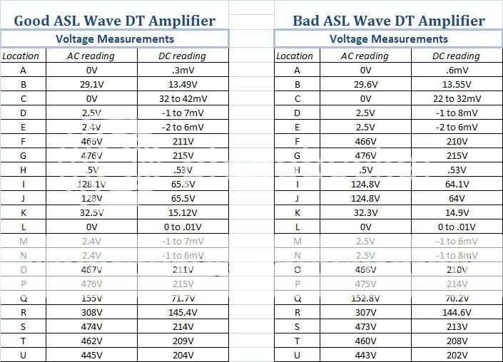
An externally hosted image should be here but it was not working when we last tested it.
OK. I think that some of you guys said you might not be around for a few days. I've been twidling my thumbs wondering what to do next and thinking about the data. I'm wodering if I should be taking readings again or additional readings to confirm my work. The only thing I could think to add to my findings was that when comparing data across the board to the schematics specs it seems like just about everything comes up short or low in voltage. I also remember that when I noticed the fluctuations in my measurements at the tube socket pins, some of the pins would respond to my taking multiple measurements back to back at the same points by the voltage increasing. Most notably at pins F and G. Any feedback is appreciated. I really want to make some progress here. I keep having to move everything off the dining room table every time it pisses my wife off. Plus what I really want to be doing is working on the new set of BLH speakers I have waiting in the wings. Thanks.
I keep having to move everything off the dining room table every time it ****es my wife off.
Wives are funny about us using the dining room table as a work bench. No sense of humor at all
 I generally put a newspaper or blanket on the table prior to hearing her bitch about it.
To me it looks like your voltage measurements are within spec.
I would replace the caps in the power supply. I assume you have already replaced C9.
We were trying to get some AC voltage measurements to try to see where the AC ripple was starting. But, it looks like his digital meter gives funny readings when a large DC bias is present. Are you sure you had the meter set to read AC volts? Do you have an extra 400~600V rated film capacitor around? Something about 0.1 uF would be perfect - something like the Auricap coupling capacitors, but it doesn't have to be that brand. You could connect the cap in series with the meter probe, and it should block the DC allowing you to measure just the residual AC.
I think he has already replaced the caps in the power supply. I thought there was a post somewhere a ways back where he suggested he had bought enough caps to replace every one in the amp twice over.
I think he has already replaced the caps in the power supply. I thought there was a post somewhere a ways back where he suggested he had bought enough caps to replace every one in the amp twice over.
Hi Guys,
Sorry I haven't had much time to spend on this over the last week. Family and what not.
Yes C9 was replaced since it was the wrong spec. It seemed that a more systematic method of diagnostics needed to be implemented (hence the extensive charts of measurements), I didn't want to just continue replacing parts unless I had at least some data that would make it suspect.
Not sure if the meter is being effected or not, not enough experience.
After the first set of voltage measurements being so bizarre, and my subsequent discovery that the bad amp was measuring completely different at several points when i rechecked it, I would say I have been very diligent in making sure I am getting the correct measurements. I've retaken them on both amps several times to confirm they were the same, the only difference i discovered is that there is a fluctuation of 2 to 3% on average at most points.
I was very certain that I was taking DC and AC when I was supposed to, that is why I set the charts up as I did. I simply made adjustments to the scale on the meter in either the AC or DC settings as needed.
I went to the local electronic supply yesterday since I thought I might as well look for the replacement 2 watt resistors that are needed for R14 and 15. I'll have to wait until the end of the week for them. But, I was able to get a .1 MFD 630V Mylar/Film capacitor to try in series with the meter for filtering out the DC as you mentioned. They didn't have any electrolytics like that in stock, will it do the job needed?
I have no problem retaking all the measurements with an without the cap in series, just need to set myself back up again.
Sorry I haven't had much time to spend on this over the last week. Family and what not.
burnedfingers said:I would replace the caps in the power supply. I assume you have already replaced C9.
Yes C9 was replaced since it was the wrong spec. It seemed that a more systematic method of diagnostics needed to be implemented (hence the extensive charts of measurements), I didn't want to just continue replacing parts unless I had at least some data that would make it suspect.
Ty_Bower said:But, it looks like his digital meter gives funny readings when a large DC bias is present. Are you sure you had the meter set to read AC volts? Do you have an extra 400~600V rated film capacitor around? Something about 0.1 uF would be perfect - something like the Auricap coupling capacitors, but it doesn't have to be that brand. You could connect the cap in series with the meter probe, and it should block the DC allowing you to measure just the residual AC.
I think he has already replaced the caps in the power supply. I thought there was a post somewhere a ways back where he suggested he had bought enough caps to replace every one in the amp twice over.
Not sure if the meter is being effected or not, not enough experience.
After the first set of voltage measurements being so bizarre, and my subsequent discovery that the bad amp was measuring completely different at several points when i rechecked it, I would say I have been very diligent in making sure I am getting the correct measurements. I've retaken them on both amps several times to confirm they were the same, the only difference i discovered is that there is a fluctuation of 2 to 3% on average at most points.
I was very certain that I was taking DC and AC when I was supposed to, that is why I set the charts up as I did. I simply made adjustments to the scale on the meter in either the AC or DC settings as needed.
I went to the local electronic supply yesterday since I thought I might as well look for the replacement 2 watt resistors that are needed for R14 and 15. I'll have to wait until the end of the week for them. But, I was able to get a .1 MFD 630V Mylar/Film capacitor to try in series with the meter for filtering out the DC as you mentioned. They didn't have any electrolytics like that in stock, will it do the job needed?
I have no problem retaking all the measurements with an without the cap in series, just need to set myself back up again.
chromenuts said:I was able to get a .1 MFD 630V Mylar/Film capacitor to try in series with the meter for filtering out the DC as you mentioned. They didn't have any electrolytics like that in stock, will it do the job needed?
I have no problem retaking all the measurements with an without the cap in series, just need to set myself back up again.
Film cap is what you want. An electrolytic will likely be polarized, and is not suitable for what you're going to do with it.
Be careful hooking the cap up in series. You almost want an extra meter probe that you can cut in half and stick the cap in the middle.
Hi Guys,
Well, I finally took the time to make some new measurements just this evening. I wish I could say I had good news, or any news for that matter.
I was able to build a new probe to use with my multimeter that I integrated the .1 MFD 630V Mylar/Film capacitor into. I actually rebuilt an entire extra red probe lead I had with better quality braided copper wire and re-soldered both probe ends and the cap in place with shrink wrap insulating. I then tested it for continuity on both sides of the cap and also tested it in the meter socket for continuity up to the cap.
I re-tested the bad amp and took all the same AC and DC measurements. Once again, they fell into a variance range of no more than 3% of the data I presented in the last post I made.
I then started taking measurements with the new filtered probe. I found that on a few of the tube pins the meter seemed to jump for an instant to some sort of reading, but then returned to zero. Ultimately, every test point I had listed measured zero or jumped too fast to read and then returned to zero.
I'm not sure if I did something wrong or what, and don't know where to go from here.
I don't think you did anything wrong with your AC measurements. With no input signal applied to the amplifier, ideally there should be no AC present anywhere after the power supply. What little residual AC is leftover should be on the order of millivolts, which is going to be too small for your meter to resolve.
Of course, now that you've verified there is no gross AC leakage through the power supply filter, where do you look next?
Of course, now that you've verified there is no gross AC leakage through the power supply filter, where do you look next?
Hi, I've been watching this thread for a while in anticipation of what could be the problem. It seems like there have been a lot of good suggestions on diagnosing the problem, but sometimes these things can be tricky and the answer isn't jumping out yet.
Just to make sure I understand, you originally had both monoblocks that make noise-
"each amplifier seemed to have a different frequency and nature to the noise coming from it. One seemed to buzz at a low frequency, the other hummed in a higher range which had been more noticeable to me at first."
Is that still the case? Your voltage charts indicate one amp is good and the other bad.
You also asked basically what is normal noise for a tube amp.
Well let me see if I can answer the noise question.
Hum can be fairly normal for a push-pull amp like the wav8. I'd say that you will most likely hear hum within a few inches to a foot from the woofers.
My experience has been that getting all the hum out of a push-pull amp can be difficult. When one tube of the push-pull pair is drawing more current than the other tube there will be a hum. I can hear this hum from about 1 foot from the speaker. I usually set the DC balance to try to minimize it. The Wave8 does not have a DC balance, so all you can do is to swap output tubes around such that each tube of the push-pull pair is producing equal amounts power. Measuring the tube power is difficult so instead it can be approximated by measuring the current flowing through the tube cathode. This is the same current that flows through R14 and R15. Divide the voltage at the cathode by its bias resistor and you have cathode current.
Latest DC reading on the "bad" amp-
Voltage@K/R14=14.9V/383ohm=38.9mA
Voltage@B/R15=13.6V/381ohm=35.7mA
There is about a 9% difference between these two tubes.
I don't *think* that this would be that audible... but you never know.
Your last voltage measurement shows that voltage@B's are about 13.5VDC and voltage@K's are about 15VDC. I'd swap only the V1 tubes between the amps to see you can get the 15's on one amp and the 13.5's on the other. See if that improves the hum.
Other than that, the most likely candidate for causing hum would be the power supply filter caps. I think you said you already changed those?
As far as the buzz goes. I built a kit tube preamp that use a diode full wave rectifier along with AC heaters. It had a higher frequency buzz problem that could be heard about 5 feet from the speaker when I was using a solid state amp. I couldn't stand it and had to change to DC heaters to make it listenable. The problem was that trash/noise from the diodes was getting interjected onto the tube filaments from the filament AC voltage supply.
Tube rush is also a regular noise from a tube amp or preamp. The best way I can describe it is a noise kind of like static or white noise coming from your tweeters. You should hear that in the neighborhood of several inches from the tweeters. This is normal.
Do any of these descriptions match the buzz and hum that you have?
-keith
The buzzing noise was isolated early on as a ground loop issue. Since then that particular amp has demonstrated very little noise. I actually compared it to my Counterpoint hybrid in terms of noise level. I would say that if both of these ASL amps functioned at that level, I would be very happy with them.
What I was left with was one mono-block ASL amp that has a very noticeable and even loud humming noise (which due to its frequency nature lends itself more to being categorized as ripple from what I have read). The noise fills the room and is easily distracting while listening to music. It is not necessary to stand close and listen to the the output of the speaker to notice this noise. No other noise is prominent from either of the amps.
I have tried swapping tube sets from one amp to the other and mixing them with no affect on the noise. I actually have some NOS tubes that I picked up with the expectation of using these amps for a period of time in the future as I experiment with building some BLH speakers, but I see no reason in installing them if there is no affect in switching out what is already working fine in one amp.
It is a very frustrating situation that I find myself in, and to be honest, I feel like I am running out of steam on this. It really shouldn't be this hard for a beginner like me.
I sought out this forum simply because I couldn't find anyone locally to even take a look at these amps. Its insane, what seems like a huge universe of enthusiasm on the internet is really a microcosm in the real world.
I only paid a few hundred dollars for these amps, and I really didn't want to have to spend a lot of money just to be able to get a taste of what is considered to be an entry level tube amplification system. At this point, I feel like I have stupidly invested in two weird, expensive looking paper weights.
I don't know about everybody else, but I found myself in the same situation as you. About 12 years ago I asked my dad about his old HHScott 296 amp. It quit working several years ago and our local shop that use to service it had gone out of business. I said I'd give it a shot and I took it home with me.
Where I live there are also no repair shops that can work on 40 year old tube amps. I decided to tackle the job myself. At one point I had taken a Circuits 101 class, I had a pretty good DMM, and had access to a scope and frequency generator at my work. So, that along with a *lot* of reading on the internet I was able to work through most of the issues. I personally don't think this stuff is easy. Heck, that's what makes it fun....not everyone can do it.
Your hum situation *should* be pretty easy to figure out but there are several things that could cause it. I just found this guitar amp debbugging guide that has a lot of good info. Check out especially the Hum link.
http://www.geofex.com/ampdbug/ampdebug.htm
-With the tube swapping you've done, we can eliminate the faulty tube and mismatched outputs.
-Faulty power supply filter caps may still be a contender.
-Faulty bias supply: N/A for this amp
-Ungrounded or not balanced filament winding: Ty spoke of this earlier. R18 & R19 should be matched *and* have a good connection to ground.
-Defective input: I think this is N/A because you say it hums without any input (...or with the input shorted?).
-Defective internal grounding: This is a possibility. I'd check every ground connection including to the chassis. Also since this has a PC board, I'd probe the ground bus at multiple points (relative to the chassis) looking for continuity. Solder traces do break.
Other prospects to getting help on this would be to take Ty up on his offer. Or take it to anyplace that services guitar amps. Do you know anyone who is into ham radio? They also may be able to help.
Before turning these into paper weights, I'd check every internal ground connection. I mean everything that is soldered to the ground buss and the chassis conn. Plus I'd take a hard look at the Filament resistors.
HTH
-keith
Hi Guys,
Sorry I haven't responded sooner. Partially life stuff, partially I needed to walk away from this for a little while.
I really appreciate you offering that Ty...it is very generous of you. I may have to take you up on the offer in the future. For now, I decided to recheck some stuff and address a few other known issues like the R14 resistor that got a little cooked. These are my notes.
I spent some time with the bad amp the other night. My first goal was to thoroughly go through it again and recheck for continuity from the chassis ground to every ground point I could find on the PCB along the ground rail, and also any other grounding points I could determine by looking at the schematic.
When I got to R18 and R19 I was careful to make sure they were grounded well, as you mentioned Keith. I also rechecked the resistance of each. As noted in the original chart of resistor data that I posted, these resistors have a spec of 100 ohms 1/2 watt. However they measure at 50ohms each. It was discussed briefly and determined that this was OK. I also got the same measurements on the amp that is working quietly.
I wasn't able to find anything that made me think I had any bad grounding connections, there really wasn't any difficulty in getting the test points to easily create a tone with the continuity tester except if I happen to touch some of the insulation instead of the metal lead on a few of the small resistors in tight spots.
There were also grounding points at the diodes that appear to be part of the power supply section of the circuit. After testing the ground points more than once here as OK, I realized I had never done any evaluation of the diodes themselves. I pulled out the DMM manual and read up on testing them. They all seem to test OK. They have a reading of about 540mV in alternating directions depending on how they appear to be mounted in the circuit. None of them read as being shorted or open in both directions, and although I don't understand completely the design of how they are integrated, I do believe the diodes themselves are fine.
At this point I sat back, scratched my head and decided to just address the cooked resistor issue. While I was working on the amp I retested the resistance across both R14 and R15 and compared it to the new resistors I had to install. I noticed that the installed resistors were down around 381 and 384, and the new resistors matched at 387. I decided to replace R15 as well so that the resistance was balanced between the two as my understanding is that these resistors are involved in biasing and I thought it to be a good idea for them to match.
After finishing the resistor replacement, I took another look at the circuit board top and bottom trying to find any visual clues as to a bad connection or something that seemed out of place. I noticed the re-drilled PCB to allow for the 12mm terminal spread on the 47uF cap that had been substituted in the C2 position. I retested C2 for ground continuity as the builder globbed on solder across the ground rail from the new hole to the pre-drilled one that was supposed to accept the 7mm spread terminals sized for the 22uF. I couldn't find a problem with the ground. I thought about replacing it since the quiet amp has properly spec'd 22uF caps in both the C1 and C2 positions, but decided to wait.
It was probably a lapse in judgment, since I realize from experience you should only change one thing at a time when repairing something. During the rest of my inspection I also noted were the Auricaps had been installed and in doing so remembered Ty's explanation of what the optimum direction for installation should be. I noted where R10 and R11 were located and compared them to the red leads on C4 and C5 and determined C5 was backwards from what it should be. I decided to change it.
After this I put the board back in place and decided to power the amp up. As the amp came up to power I immediately noticed a static like noise along with the hum. I rolled my eyes, and shut it down.
I took the amp back apart and reinspected my work several times under bright light. I couldn't find anything. I had only done the simplest soldering repair on three items on the board. I searched everywhere for any loose beads of solder or anything else. I found nothing. I wondered if I had affected something while swinging the PCB out of the chassis, and thought about the events surrounding R14 cooking. I made a mental note that the sound that came out of the speaker was different from the "motor-boating" noise that had resulted from finding the bead of solder creating a short under the tube socket when R14 had cooked. I thought that maybe my problem was a wire or something shifting when I was swinging the board out to work on it. I decided to put it back together and try powering it up again while carefully trying to monitor the heat being generated by R14 and R15 and keeping an eye out for anything that might be heating up.
Turning the amp back on generated the static noise again. I was able to sense heat being generated on R14 after a little while so I powered the amp back off. It wasn't a lot of heat, but enough for me to not be able to hold my finger on it indefinitely. I thought I noticed a tapering off of the noise before I shut the amp down. Nothing smoked, or felt very hot as I continued to explore inside the amp carefully. I noticed that R15 also had a certain amount of warmth to it, and thought that perhaps some heat was normal coming from the ceramic insulation. I decided to power the amp up again and compare the heat between R14 and R15.
Powering the amp up again gave a very noticeable decrease in the static noise. I noted it, and focused on the resistors. They came up to heat, and while monitoring them I noticed the static eventually disappeared. What the heck?! I noticed that the resistors seem to stabalize at a certain heat level after a little while and that in general I could keep my finger on R14 for a shorter period of time than on R15. There didn't seem to be any indication of them continuing to heat up more and cooking.
I redirected my attention to the issue of trying to come up with another possibility for the static. I wondered if a residual charge in the Auricap could have the affect of creating the static after reversing it as I did in the circuit. I felt around and started shifting easily accessible wires to see if they created any noise. Eventually I noticed some noise when I played with the input wire coming from the RCA jack. I grabbed it from the outside were it was shorted out with the cable plug I had built for that purpose and turned it and shifted it. This resulted in a considerable amount of noise, although I can't say it was defintely the same noise I heard when powering the amp up, it was also static. I removed my shorting plug, and in doing so I noticed that the hum level of the amp seemed to increase in volume.
I powered the amp back down and reinspected the RCA jack from the inside, as I had noticed it had a certain amount of play in it. I compared it to the good amp, which also had about the same amount of play. I decided to plug the good amp in and perform the same test at its RCA jack to rule out my input shorting plug. I wasn't able to reproduce the same noise. I believe the noise was a result of the center contact of the RCA jack in the bad amp intermittently shorting or a bad contact somewhere in the internal signal wire.
I tried powering up the bad amp again today. The amp will make the same static noise from a cold start up. The noise stops after a short time. I believe it is possible to create small intermittent bursts of the same noise by playing with the signal cable. I'm not convinced this is the source of my hum, but the jack should probably be replaced. That is where I stand. Sorry for such a long post.
BTW. I took voltage measurements across the board after the new resistor install at R14 and R15. Many of them seem to have been affected slightly by the new resistors.
Sorry I haven't responded sooner. Partially life stuff, partially I needed to walk away from this for a little while.
Ty_Bower said:I'd like to discuss a way we might be able to arrange to get your amp to me, and I'll take a look at it. Send me an email if you are interested.
I really appreciate you offering that Ty...it is very generous of you. I may have to take you up on the offer in the future. For now, I decided to recheck some stuff and address a few other known issues like the R14 resistor that got a little cooked. These are my notes.
keithandy said:-Faulty power supply filter caps may still be a contender.
-Ungrounded or not balanced filament winding: Ty spoke of this earlier. R18 & R19 should be matched *and* have a good connection to ground.
-Defective input: I think this is N/A because you say it hums without any input (...or with the input shorted?).
-Defective internal grounding: This is a possibility. I'd check every ground connection including to the chassis. Also since this has a PC board, I'd probe the ground bus at multiple points (relative to the chassis) looking for continuity. Solder traces do break.
I spent some time with the bad amp the other night. My first goal was to thoroughly go through it again and recheck for continuity from the chassis ground to every ground point I could find on the PCB along the ground rail, and also any other grounding points I could determine by looking at the schematic.
When I got to R18 and R19 I was careful to make sure they were grounded well, as you mentioned Keith. I also rechecked the resistance of each. As noted in the original chart of resistor data that I posted, these resistors have a spec of 100 ohms 1/2 watt. However they measure at 50ohms each. It was discussed briefly and determined that this was OK. I also got the same measurements on the amp that is working quietly.
I wasn't able to find anything that made me think I had any bad grounding connections, there really wasn't any difficulty in getting the test points to easily create a tone with the continuity tester except if I happen to touch some of the insulation instead of the metal lead on a few of the small resistors in tight spots.
There were also grounding points at the diodes that appear to be part of the power supply section of the circuit. After testing the ground points more than once here as OK, I realized I had never done any evaluation of the diodes themselves. I pulled out the DMM manual and read up on testing them. They all seem to test OK. They have a reading of about 540mV in alternating directions depending on how they appear to be mounted in the circuit. None of them read as being shorted or open in both directions, and although I don't understand completely the design of how they are integrated, I do believe the diodes themselves are fine.
At this point I sat back, scratched my head and decided to just address the cooked resistor issue. While I was working on the amp I retested the resistance across both R14 and R15 and compared it to the new resistors I had to install. I noticed that the installed resistors were down around 381 and 384, and the new resistors matched at 387. I decided to replace R15 as well so that the resistance was balanced between the two as my understanding is that these resistors are involved in biasing and I thought it to be a good idea for them to match.
After finishing the resistor replacement, I took another look at the circuit board top and bottom trying to find any visual clues as to a bad connection or something that seemed out of place. I noticed the re-drilled PCB to allow for the 12mm terminal spread on the 47uF cap that had been substituted in the C2 position. I retested C2 for ground continuity as the builder globbed on solder across the ground rail from the new hole to the pre-drilled one that was supposed to accept the 7mm spread terminals sized for the 22uF. I couldn't find a problem with the ground. I thought about replacing it since the quiet amp has properly spec'd 22uF caps in both the C1 and C2 positions, but decided to wait.
It was probably a lapse in judgment, since I realize from experience you should only change one thing at a time when repairing something. During the rest of my inspection I also noted were the Auricaps had been installed and in doing so remembered Ty's explanation of what the optimum direction for installation should be. I noted where R10 and R11 were located and compared them to the red leads on C4 and C5 and determined C5 was backwards from what it should be. I decided to change it.
After this I put the board back in place and decided to power the amp up. As the amp came up to power I immediately noticed a static like noise along with the hum. I rolled my eyes, and shut it down.
I took the amp back apart and reinspected my work several times under bright light. I couldn't find anything. I had only done the simplest soldering repair on three items on the board. I searched everywhere for any loose beads of solder or anything else. I found nothing. I wondered if I had affected something while swinging the PCB out of the chassis, and thought about the events surrounding R14 cooking. I made a mental note that the sound that came out of the speaker was different from the "motor-boating" noise that had resulted from finding the bead of solder creating a short under the tube socket when R14 had cooked. I thought that maybe my problem was a wire or something shifting when I was swinging the board out to work on it. I decided to put it back together and try powering it up again while carefully trying to monitor the heat being generated by R14 and R15 and keeping an eye out for anything that might be heating up.
Turning the amp back on generated the static noise again. I was able to sense heat being generated on R14 after a little while so I powered the amp back off. It wasn't a lot of heat, but enough for me to not be able to hold my finger on it indefinitely. I thought I noticed a tapering off of the noise before I shut the amp down. Nothing smoked, or felt very hot as I continued to explore inside the amp carefully. I noticed that R15 also had a certain amount of warmth to it, and thought that perhaps some heat was normal coming from the ceramic insulation. I decided to power the amp up again and compare the heat between R14 and R15.
Powering the amp up again gave a very noticeable decrease in the static noise. I noted it, and focused on the resistors. They came up to heat, and while monitoring them I noticed the static eventually disappeared. What the heck?! I noticed that the resistors seem to stabalize at a certain heat level after a little while and that in general I could keep my finger on R14 for a shorter period of time than on R15. There didn't seem to be any indication of them continuing to heat up more and cooking.
I redirected my attention to the issue of trying to come up with another possibility for the static. I wondered if a residual charge in the Auricap could have the affect of creating the static after reversing it as I did in the circuit. I felt around and started shifting easily accessible wires to see if they created any noise. Eventually I noticed some noise when I played with the input wire coming from the RCA jack. I grabbed it from the outside were it was shorted out with the cable plug I had built for that purpose and turned it and shifted it. This resulted in a considerable amount of noise, although I can't say it was defintely the same noise I heard when powering the amp up, it was also static. I removed my shorting plug, and in doing so I noticed that the hum level of the amp seemed to increase in volume.
I powered the amp back down and reinspected the RCA jack from the inside, as I had noticed it had a certain amount of play in it. I compared it to the good amp, which also had about the same amount of play. I decided to plug the good amp in and perform the same test at its RCA jack to rule out my input shorting plug. I wasn't able to reproduce the same noise. I believe the noise was a result of the center contact of the RCA jack in the bad amp intermittently shorting or a bad contact somewhere in the internal signal wire.
I tried powering up the bad amp again today. The amp will make the same static noise from a cold start up. The noise stops after a short time. I believe it is possible to create small intermittent bursts of the same noise by playing with the signal cable. I'm not convinced this is the source of my hum, but the jack should probably be replaced. That is where I stand. Sorry for such a long post.
BTW. I took voltage measurements across the board after the new resistor install at R14 and R15. Many of them seem to have been affected slightly by the new resistors.
I had watched this thread for a while, but do to being busy with life, I have not logged on for many weeks. Sorry to hear you are still having problems with the amp. I own two of these; purchased them new in 2000 or 2001??? They were $99 each and the quality is worth $99 or less. I had problems with mine out of the box; check your grounds (which you did) and check your RCA input connectors. I had one shorting or not making contact with chassis ground; I can't remember which. Also, the banana connectors on mine are crap. As I recall, the + on one of the outputs was shorted to the metal on the chassis.
If you need me to check the earth ground to signal ground resistance, please let me know. Since I can't remember, I will be more than happy to check this for you. I wish I had time to help troubleshoot with you. If the problem continues, I will try to make time to help.
Dave
If you need me to check the earth ground to signal ground resistance, please let me know. Since I can't remember, I will be more than happy to check this for you. I wish I had time to help troubleshoot with you. If the problem continues, I will try to make time to help.
Dave
- Status
- This old topic is closed. If you want to reopen this topic, contact a moderator using the "Report Post" button.
- Home
- Amplifiers
- Tubes / Valves
- Newbie and ASL Wave 8 problems